Transcription of DataSheet Solid State Relay Timer - Crydom
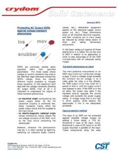
1 DataSheet Solid State Relay Timer SeriesOneDR Timer 6 Amp AC and DC rated output Compact size (11mm wide). Dual SCR or MOSFET output AC/DC control Zero-crossing (resistive loads) or random-fire (inductive loads) AC output Timer status LED indicator UL listed, HP rated 8 Industry standard fuctions (A/At, B, C, D/Di, H/Ht, L/Li, Ac and Bw). PRODUCT SELECTION. Control Voltage AC Output DC Output 12-24 VAC/DC DRTx24D06x DRTx06D06. 90-140 VAC/DC DRTx24B06x 180-280 VAC/DC DRTx24A06x AVAILABLE OPTIONS. Operating Voltage 06: 60 VDC Rated Load Current Series 24: 280 VAC 06: 6 Amps DRT A 24 D 06 R. Timing Function Control Voltage Switching Type A: A/At, Delay on Make D: 12-24 VAC/DC (24 suffix only). AC. B: Single Shot A: 180-240 VAC/DC Output Blank: Zero Voltage Turn-On C: Delay on Break B: 90-140 VAC/DC Only R: Random Turn-On H: H/Ht, Interval L: L/Li, Repeat Cycle Required for valid part number U: Multifunction (A/At, H/Ht, D/Di, For options only and not required for valid part number B, C, Ac & Bw) * Not all part number combinations are available.
2 Contact Crydom Technical Support for information on the availability of a specific part number. OUTPUT SPECIFICATIONS (1). Description DRTx24 DRTx06. Operating Voltage 24-280 VAC (47-440Hz) 1-48 VDC. Transient Overvoltage [Vpk] 600 60 VDC. Rated Load Current (2) 6 Arms 6A. Rated Load Current {UL508 Motor Controller} (2) [Arms] Arms - Minimum Load Current 150 mArms mA. Maximum Off- State Leakage Current @ Rated Voltage mArms mA. Minimum Off- State dv/dt @ Maximum Rated Voltage [V/ sec] (3) 500 - Maximum Surge Current (AC output 1 cycle. DC output 10ms) 285/300 Apk (50/60Hz) 60 A. Maximum I t for Fusing [A sec] 410/375 (50/60Hz) - Maximum On- State Voltage Drop @ Rated Current [Vpk] VDC. Maximum On- State Resistance (RDS-ON) [Ohms] - HP rating UL 508/IEC60947[HP (KW)]: 240 VAC 1/3 ( ) - IEC 62314 LC-A [FLA] 6A - IEC 62314 LC-B [Kw] - Wire Size min/max ( Solid /stranded) [AWG/ IEC mm ] (4) 22/12 [ ] 22/12 [ ].
3 Output Terminal Screw Torque [in lb (Nm)] ( ) ( ). Do not forget to visit us at: Copyright 2017 Crydom Inc. Specifications subject to change without notice. DataSheet Solid State Relay Timer INPUT SPECIFICATIONS (1). Description DRTxxxD06 DRTx24A06 DRTx24B06. Control Voltage Range 12-24 VAC/DC 180-280 VAC/DC 90-140 VAC/DC. Must Turn-Off Voltage 1 VAC/DC 20 VAC/DC 10 VAC/DC. Min Input Current @ Min Voltage (AC/DC) (for on- State ) mA (5) mA mA. Maximum Input Current @ Maximum Voltage mA (6) mA mA. Nominal Input Impedance 2K Ohms(7) 25K ohms 12K ohms Wire Size min-max ( Solid /stranded) [AWG/ IEC mm ] (4) 22-16 / 22-16 / 22-16 / LED Status Indicator (Color) Yes (green) Yes (green) Yes (green). Input Terminal Screw Torque [in lb (Nm)] ( ) ( ) ( ).
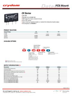
4 Maximum turn-on/off time See note (9) See note (9) See note (9). GENERAL SPECIFICATIONS. Description Parameters Dielectric Strength, Input/Output/Base (50/60Hz) 3750 Vrms (8). Minimum Insulation Resistance (@ 500 VDC) 109 Ohm Maximum Capacitance, Input/Output 10 pF. Ambient Operating Temperature Range -30 to 80 C. Ambient Storage Temperature Range -40 to 125 C. Weight (typical) oz (50 g). Housing Material UL 94 V0 Self-extinguishing Terminal Finish Sulfamate Nickel Humidity 5 - 85% Non condensing RoHS Exemption #'s 5(a), 7(a), 7(c)-I. WIRING DIAGRAM. (+ / ). A2. Load ( ). INPUT. CONTROL +3/A1 Y1 +1/L1. AC/DC CONTROL A1. Status VOLTAGE. AC Output (Input). Indicator Timer . Y1. 4/A2 2/T1. ( / ) ( ). (+ / ) (10).
5 Load (+). INPUT. +3/A1 +1/L1. CONTROL Y1. L1 T1. Status DC Output Indicator d Timer Load AC/DC SUPPLY. 4/A2 2/T1. (OUTPUT) Loa ( / ) ( ). Do not forget to visit us at: Copyright 2017 Crydom Inc. Specifications subject to change without notice. DataSheet Solid State Relay Timer Timer SETTINGS & RANGES. Timer Settings Timing Ranges (11). Identification Timing Range Identification 1s s to 1 s Timing Function INPUT. 10 s 1 s to 10 s STATUS. Side View Front View 1 min min to 1 min 10 min 1 min to 10 min U 1s 10s AH 8 9 10. 1m 5 6 7. 1h h to 1 h BC. Multifunction 10m1. h Di AcBw 10 h 1 h to 10 h 4. 10h100. [A/At, H/Ht, D/Di, h 1 2 3. B, C, Ac, Bw] Range Function Fine Adjustment 100 h 10 h to 100 h 1s 10s 1s 10s 8 9 10 8 9 10.
6 L. 1m 1m 5 6 7. 5 6 7. 10m1. 10m1. Repeat Cycle h h 4. 4. 10h100 10h100. h h 1 2 3 1 2 3. T on T off Fine Adjustment A. Delay on Make H 1s 10s 8 9 10. 1m 5 6 7. Interval 10m1. h 4. 10h100 1 2 3. h B Range Fine Adjustment Single Shot C. Delay on Break Flat side indicates selection GENERAL NOTES. (1) All parameters at 25 C unless otherwise specified. (2) See derating curves. (3) Off- State dv/dt test method per EIA/NARM standard RD-443, paragraph (4) For UL Listing, must use wire rated @ 75 C. (5) For DC output model minimum current spec is (AC/DC). (6) For DC output model maximum current spec is (AC/DC). (7) For DC output mode, spec is 1K. (8) For DC output model, spec is 2500V. (9) Activation Time = 65ms / Deactivation Time = 100 ms.
7 (10) Inductive loads must be diode suppressed to prevent damage to output. (11) Timing accuracy 10%. Additional functions and time ranges are also available, please contact your local authorized Crydom Distributor, Representative or Crydom Sales office and request information about our custom products. (12) Do not apply a push force greater than ( ) and Stop torque 4 Ncm. (13) Do not apply a push/pull force greater than 5N( ) and torque 20Nm. Do not forget to visit us at: Copyright 2017 Crydom Inc. Specifications subject to change without notice. DataSheet Solid State Relay Timer MECHANICAL SPECIFICATIONS. Tolerances: in / mm All dimensions are in: inches [millimeters] [ ]. [ ] [ ]. (12). [ ]. 4/A2 2/T1.
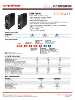
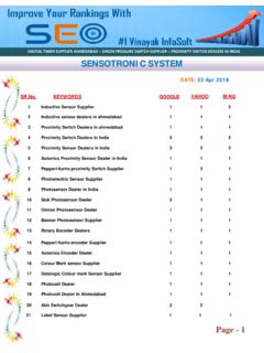
8 DRTL06D06. 4WB8. [ ] S OL I D S TAT E T I M E R. INPUT 12-24 VDC. General Use 60 VDC/6 Arms +3/A1 @40 C Ambient Temperature +1/L1. IND. CONT. EQ. Y1. (13). INPUT. STATUS. [ ]. [ ]. [ ]. THERMAL DERATE INFORMATION. 6. 5. Load Current (Amps). 4. 3. 2. 1. 0. 0 10 20 30 40 50 60 70 80. Ambient Temperature ( C). Installed single unit, distance to adjacent components 11 mm Multiple Units No Spacing Do not forget to visit us at: Copyright 2017 Crydom Inc. Specifications subject to change without notice. DataSheet Solid State Relay Timer LED STATUS FUNCTION. LED Status by Function Function Control Voltage Y1 Timing Output State LED Status Notes At function is identical to the A function except when Y1 is connected to A1 timing is paused.
9 When Y1 is Off Off Off Off removed timing resumes until Relay times out. To reset Timer remove control power. A/At On On Off Long Flashes C C t1 t2 t3. Delay On Make A T At Y1. On Timed Out On On L T=t1+t2+t3. L. Off Off Off Ht function is identical to the H function except when Y1 is connected to A1 timing is paused. When Y1 is Off removed timing resumes until Relay times out. To reset Timer remove control power. H/Ht On On On Long Flashes C C t1 t2 t3. Interval H T Ht Y1. T=t1+t2+t3. On Timed Out Off Short Flashes L L. To select between on time (Di) first or off time (D) first Y1 is connected. Default is On time (Di) first, for Off Off Off Off Off time (D) first connect Y1. Equal On/Off time. D/Di C C.
10 Repeat Cycle Di On On On/Off Long Flashes/Short Flashes D A1Y1. T T T T T T T T T T. L L. To select between on time (Li) first or off time (L) first Y1 is connected A1. Default is On time (Li) first, for Off Off Off Off Off time (L) first connect Y1 to A1. Time delay is independent of each other. L/Li C C. Repeat Cycle L A1Y1 Toff Ton Toff Ton Toff Li Ton Toff Ton Toff On On On/Off Long Flashes/Short Flashes L L. Off Open Off Off Off C. B On Open Off Off Short Flashes Y1 switch can be momentary or maintained to A1. To Y1. Single Shot On Closed On On Long Flashes reset Timer after Relay has timed out Y1 has to be B T. opened. L. On Closed Timed Out Off Short Flashes Off Open Off Off Off On Open Off Off Short Flashes Y1 switch to A1 must be momentary for timing to C.