Transcription of Datasheet Ultrasonic Sensor with ... - Banner Engineering
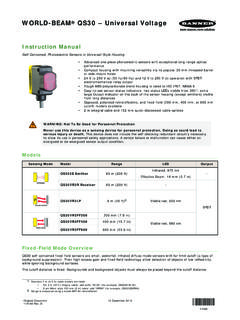
1 DatasheetUltrasonic Sensor with TEACH-Mode Configuration 1, 2 and 3 m ( , , and ft) versions with short dead zones(10% of max range) Built-in temperature compensation Fast, easy-to-use TEACH-Mode programming; no potentiometeradjustments Configure with either a positive or negative analog output slope Remote TEACH for security and convenience Wide operating temperature range of 40 to +70 C ( 40 to +158 F) Choose either 0 to 10V dc or 4 to 20 mA output model Compact, self-contained, right-angle Sensor package with fullyencapsulated electronicsModelsModelsRange and FrequencyCable1 Supply VoltageAnalog OutputResponse TimeT30 UXUA100 mm to 1 m ( in to 39 in)224 kHzStandard 2 m( ft) cable10 to 30 V dc0 to 10 V dc45 ms or 105 ms selectableT30 UXIA4 to 20 mAT30 UXUB200 mm to 2 m ( in to 78 in)174 kHz0 to 10 V dc92 ms or 222 ms selectableT30 UXIB4 to 20 mAT30 UXUC300 mm to 3 m ( in to 118 in)
2 114 kHz0 to 10 V dc135 ms or 318 ms selectableT30 UXIC4 to 20 mAWARNING: Not To Be Used for Personnel ProtectionNever use this device as a sensing device for personnel protection. Doing so could lead toserious injury or death. This device does not include the self-checking redundant circuitry necessaryto allow its use in personnel safety applications. A Sensor failure or malfunction can cause either anenergized or de-energized Sensor output U-GAGE T30UX is an easy-to-use Ultrasonic Sensor with extendedrange and built-in temperature compensation. Simple push buttonconfiguration provides flexibility for a variety of indicator LEDs communicate the status of the Sensor . The Green Power LED ON indicates that the Sensor is in Run Mode (the Sensor snormal operating condition).
3 The Red Signal LED indicates the targetsignal strength. The Amber Output LED indicates that the output isenabled and the Sensor is receiving a signal within the window limits. TheAmber Mode LED indicates the currently selected mode(fast or slow).Power ON/OFFLED (Green)Discrete OutputLED (Amber)Signal StrengthLED (Red)Mode LEDs(Amber)Figure 1. Features1 Only standard 2 m ( ft) cable models are listed. To order the 4-Pin Euro-Style integral QD, add suffix Q8 to the model number (for example,T30 UXUAQ8). To order the 150 mm (6 in) PUR pigtail cable with 4-Pin threaded Euro-Style QD, add suffix QPMA to the model number (forexample, T30 UXUAQPMA). To order the 9 m (30 ft) cable, add suffix W/30 to the model number (for example, T30 UXUA W/30).
4 A modelwith a QD connector requires a mating cable; see Quick-Disconnect Cables on page T30UX series with Analog Output Original Document141958 Rev. E19 September 2016141958 Principles of OperationUltrasonic sensors emit one or multiple pulses of Ultrasonic energy, which travel through the air at the speed of sound. Aportion of this energy reflects off the target and travels back to the Sensor . The Sensor measures the total time requiredfor the energy to reach the target and return to the Sensor . The distance to the object is then calculated using thefollowing formula: D = ct 2D = distance from the Sensor to the targetc = speed of sound in airt = transit time for the Ultrasonic pulseTo improve accuracy, an Ultrasonic Sensor may average the results of several pulses before outputting a new EffectsThe speed of sound is dependent upon the composition, pressure and temperature of the gas in which it is traveling.
5 Formost Ultrasonic applications, the composition and pressure of the gas are relatively fixed, while the temperature air, the speed of sound varies with temperature according to the following approximation:In metricunits:Cm/s = 20 273 + TC In English units: ft/s = 49 460 + TFCCm/s = speed of sound in meters per secondCft/s = speed of sound in feet per secondTC = temperature in CTF = temperature in FTemperature CompensationChanges in air temperature affect the speed of sound, which in turn affects the total time for the echo measured by thesensor. An increase in air temperature shifts both sensing window limits closer to the Sensor . Conversely, a decrease in airtemperature shifts both limits farther away from the Sensor . This shift is approximately of the limit distance for a 20 C change in T30UX series Ultrasonic sensors are temperature compensated.
6 This reduces the error due to temperature by about90%. The Sensor will maintain its window limits to within over the -40 to +70 C ( 40 to +158 F) operatingrange of the : Exposure to direct sunlight can affect the Sensor s ability to accurately compensate for changesin temperature. If the Sensor is measuring across a temperature gradient, the compensation will be InstructionsSensor ConfigurationTwo TEACH methods may be used to configure the Sensor : Teach individual minimum and maximum limits, or Use Auto-Window feature to center a sensing window around the taught Sensor may be configured either via its push button, or via a remote switch. Remote configuration also may be used todisable the push button, preventing unauthorized personnel from adjusting the configuration settings.
7 To access thisfeature, connect the white wire of the Sensor to 0V dc, with a remote configuration switch between the Sensor and is accomplished by following the sequence of input pulses. The duration of each pulse (corresponding to apush button click ), and the period between multiple pulses, are as T : seconds < T < secondsRemote line configuration requires a greater than 1 second pause between pulse Setup - Response SpeedAnalog Sensor models can be set up for either Fast or Slow response time. A button click or pulse on the remote line s < T < Enter Response Speed Mode setup mode. U-GAGE T30UX series with Analog - Tel: +1-763-544-3164P/N 141958 Rev. EMethodActionResultPush ButtonPush and hold MODE push button for > 2 LED: OFFMode LED: Flashing Amber showspreviously selected modeRemote InputDouble-pulse the remote line.
8 TTTP ower LED: OFFMode LED: Flashing Amber showspreviously selected mode2. Select the ButtonClick the MODE button to cycle to the correct selection: Fast or LED: OFFMode LED: Amber flashes to indicatecurrently selected mode (120 second timeout2)Remote InputSingle-pulse to select Slow; double-pulse to select LED: ON GreenMode LED: ON Amber shows selectedmode ( Sensor returns to RUN mode)3. Save and return to Run ButtonPush and hold the MODE button for more than 2 LED: ON GreenMode LED: ON Amber for selected modeRemote InputNo action is required; the Sensor will return to Run OutputThe U-GAGE T30UX series Sensor may be configured for either a positive or a negative output slope, based on whichcondition is taught first (see Figure 2 on page 3).
9 If the near limit is taught first, the slope will be positive; if the farlimit is taught first, the slope will be negative. Banner s scalable analog output automatically distributes the output signalover the width of the programmed sensing U-GAGE T30UX also features a 2-second hold upon loss of the received signal, which is useful for harsh and unstableapplications. In the event of signal loss for longer than 2 seconds, the analog output goes to mA or 0V dc, which maybe used to trigger an ModelsTarget PositionPositiveSlopeNearWindowFarWindow Analog Output (mA)204 NegativeSlopeVoltage-Sourcing ModelsTarget PositionPositiveSlopeNearWindowFarWindow Voltage Output (V dc)100 NegativeSlopeFigure 2. Positive and Negative Output SlopesTeaching Minimum and Maximum LimitsGeneral Notes on Teaching The Sensor returns to RUN mode if the first TEACH condition is not registered within 120 seconds after the initial 2second hold on the Analog Sensor will revert to previously saved configuration and return to RUN mode if TEACH is inactive for 120 seconds after the initial 2 secondhold on push buttonU-GAGE T30UX series with Analog Output P/N 141958 Rev.
10 - Tel: +1-763-544-31643 To exit TEACH mode without saving any changes, press and hold the Analog button or remote line longer than 2seconds (before teaching the second limit). The Sensor reverts to the last saved limits. After the first limit is taught, the Sensor remains in TEACH mode until the TEACH sequence is finished or exited bya 2 second hold on the Analog button or remote line. A button click or pulse on the remote line is: s < T < Enter TEACH ButtonPush and hold the Analog push button longer than 2 LED: OFFO utput LED: ONRemote InputNo action required; Sensor is ready for first limit Teach the first ButtonPosition the target for the first limit (120 second time out).Signal LED: Must be ON Red or FlashingRed3 Click the Analog AcceptedPower LED: OFFO utput LED: FlashingTeach Not AcceptedOutput LED: ONRemote InputPosition the target for the first LED: Must be ON Red or FlashingRed3 Single-pulse the remote line.