Example: marketing
Datasheet - XLSEMI
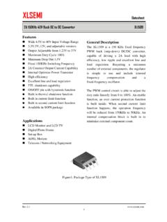
Buck constant current driver General Description The XL4301 is a 180KHz fixed frequency PWM buck (step-down) DC/DC converter, apable of driving a 2.5A load with high efficiency, low ripple and excellent line and Requiring a minimum regulator is simple to use and include frequency compensation and a
Tags:
Information
Domain:
Source:
Link to this page:
Documents from same domain

400KHz 60V 3A Switching Current Boost / Buck …
www.xlsemi.comXL6008 400KHz 60V 3A Switching Current Boost / Buck-Boost / Inverting DC/DC Converter Rev 1.2 www.xlsemi.com

180KHz 60V 5A Switching Current Boost / Buck …
www.xlsemi.comXL6019 180KHz 60V 5A Switching Current Boost / Buck-Boost / Inverting DC/DC Converter Rev 1.1 www.xlsemi.com

400KHz 60V 2A Switching Current Boost / Buck …
www.xlsemi.comXL6007 400KHz 60V 2A Switching Current Boost / Buck-Boost / Inverting DC/DC Converter Rev 1.2 www.xlsemi.com

Datasheet 5A 180KHz 36V Buck DC to DC Converter …
www.xlsemi.comDatasheet 5A 180KHz 36V Buck DC to DC Converter XL4015 Rev 1.5 www.xlsemi.com

Datasheet 4A 300KHz 32V Buck DC to DC …
www.xlsemi.comDatasheet 4A 300KHz 32V Buck DC to DC Converter XL4003 Rev 2.3 www.xlsemi.com

Features General Description - xlsemi.com
www.xlsemi.comDatasheet 4A 180KHz 36V Buck DC to DC Converter XL4013

Features General Description - xlsemi.com
www.xlsemi.comDatasheet 3A 150KHz 40V Buck DC to DC Converter XL1507

Features General Description - xlsemi.com
www.xlsemi.comDatasheet 3A 380KHz 18V Buck DC to DC Converter XL1530 Rev 1.0 www.xlsemi.com
Features General Description - xlsemi.com
www.xlsemi.comDatasheet 2A 150KHz 40V Buck DC to DC Converter XL1509 Rev 2.0 www.xlsemi.com

Features General Description - xlsemi.com
www.xlsemi.comDatasheet 3A 150KHz 40V Buck DC to DC Converter XL2596 Rev 2.4 www.xlsemi.com
Related documents
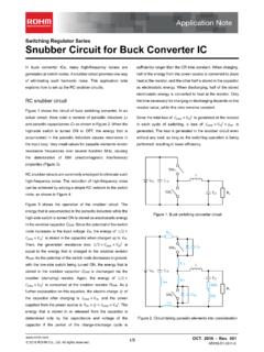
Snubber Circuit for Buck Converter IC : Power Management
fscdn.rohm.comthe time necessary for charging or discharging depends on the resistor value, while this ratio remains constant. Since the total loss of % Ì Ç » H 8 Â Ç is generated at the resistor in each cycle of switching, a loss of % Ì Ç » H 8 Â Ç H B Ì Ð is generated. The loss is generated in the snubber circuit even
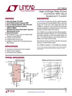
LTC3824 – High Voltage Step-Down Controller With 40µA ...
www.analog.comtime. The switching frequency can be programmed up to 600kHz and is easily synchronizable. Other features include current limit, soft-start, micropower shutdown, and Burst Mode disable. The LTC3824 is available in a 10-lead MSE power package. 5V/2A Buck Converter n Wide Input Range: 4V to 60V n Current Mode Constant Frequency PWM
Zero Voltage Switching Resonant Power Conversion
www.ti.comZero Voltage Switching Overview Zero voltage switching can best be defined as conventional square wave power conversion during the switch’s on-time with “resonant” switching transitions. For the most part, it can be considered as square wave power utilizing a constant off-time control which varies the conversion frequency, or on-time to ...
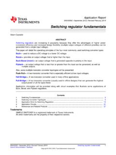
Switching regulator fundamentals (Rev. C)
www.ti.comON time of the switch. 2 Switching Converter Topologies The most commonly used DC/DC converter circuits will now be presented along with the basic principles of operation. 2.1 Buck Regulator The most commonly used switching converter is the Buck, which is used to down-convert a DC voltage to a lower DC voltage of the same polarity.

DC to DC Converters
www.site.uottawa.caInverting Buck Boost Converter • The last and most important type of switching regulator is the buck-boost converter. In this converter, the buck and boost topologies covered earlier are combined into one. A buck-boost converter is also built using the same components used in the converters covered before. The inductor in this
AN149 Modeling and Loop Compensation Design of …
www.analog.comground in the buck converter. The common terminal “c” is connected to a current source, which is the inductor in the buck converter. To change the time-variant SMPS into a time-invariant system, the 3-terminal PWM cell averagemodelingmethod can be applied by changing the active switch Q to an aver-

ROHM Switching Regulator Solutions Synchronous Buck ...
fscdn.rohm.comROHM Switching Regulator Solutions Synchronous Buck Converter Controller BD9611MUV-EVK-001 Description Using a synchronous rectified step-down DC/DC converter IC BD9611MUV BD 9611MUV-EVK-001 evaluation board 15.0 V ~ output a 24 V input voltage 12.0 V. Provides 10.0A output current. Output current is possible with current settings by selecting
Buck Converter Design - Mouser
www.mouser.deSwitching MOSFET The buck converter is a hard-switched topology. The switching MOSFET has to resemble an ideal switch, i.e. being low ohmic and fast switching. As with the synchronous rectifier MOSFET, the FOM is setting limits to as far one can come to an ideal switch. For a buck converter switch, the following are major MOSFET selection ...