Example: bankruptcy
Zero Voltage Switching Resonant Power Conversion
Zero Voltage Switching Overview Zero voltage switching can best be defined as conventional square wave power conversion during the switch’s on-time with “resonant” switching transitions. For the most part, it can be considered as square wave power utilizing a constant off-time control which varies the conversion frequency, or on-time to ...
Tags:
Information
Domain:
Source:
Link to this page:
Documents from same domain

LM136-2.5,LM236-2.5,LM336-2 - TI.com
www.ti.comLM136-2.5/LM236-2.5/LM336-2.5V Reference Diode General Description The LM136-2.5/LM236-2.5 and LM336-2.5 integrated cir-cuits are …

SimpleLink™ CC3120, CC3220 Wi-Fi ... - Texas …
www.ti.comUser User x x x x x x x x x x x x x x x x x x x x Application Servers Vendor IoT Devices Internet Introduction www.ti.com 4 SWRA509A–February 2017–Revised March 2017 Submit Documentation Feedback

www.ti.com SNVS749F - Texas Instruments
www.ti.comLM136-2.5-N SNVS749F – MAY 1998– REVISED APRIL 2013 www.ti.com Typical Performance Characteristics (continued) Temperature Drift Figure 13. …

MSP430x2xx Family User's Guide (Rev. J) - TI.com
www.ti.comMSP430x2xx Family User's Guide Literature Number: SLAU144J December 2004– Revised July 2013

1.8-V Micropower CMOS Operational Amplifier …
www.ti.com5 OPA2333-HT www.ti.com SBOS483I –JULY 2009–REVISED MAY 2015 Product Folder Links: OPA2333-HT Copyright © 2009–2015, Texas Instruments Incorporated Submit Documentation Feedback

LMC6482 CMOS Dual Rail-To-Rail Input and Output ...
www.ti.comLMC6482 www.ti.com SNOS674E –NOVEMBER 1997–REVISED APRIL 2015 5 Pin Configuration and Functions D, DGK and P Packages 8-Pin SOIC, VSSOP and PDIP (Top View) Pin Functions PIN TYPE DESCRIPTION NO.

OPAx354 250-MHz, Rail-to-Rail I/O, CMOS …
www.ti.comOPA354 IN +IN V OUT V+ V Product Folder Order Now Technical Documents Tools & Software Support & Community Reference Design An IMPORTANT NOTICE at the end of this data sheet addresses availability, warranty, changes, use …

Analog linearization of resistance temperature …
www.ti.com21 Analog Applications Journal Texas Instruments Incorporated 4Q 2011 www.ti.com/aaj High-Performance Analog Products …

TMS320C28x DSP/BIOS 5.x Application …
www.ti.comSPRU625L—August 2012 API Functional Overview 9 Submit Documentation Feedback www.ti.com Naming Conventions 1.2 Naming Conventions The format for a DSP/BIOS operation name is a 3- or 4-letter prefix for the module that contains the

WL18x7MOD WiLink™ 8 Dual-Band Industrial …
www.ti.comProduct Folder Order Now Technical Documents Tools & Software Support & Community Reference Design An IMPORTANT NOTICE at the end of this data sheet addresses availability, warranty, changes, use in safety-critical applications,
Related documents
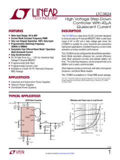
Snubber Circuit for Buck Converter IC : Power Management
fscdn.rohm.comthe time necessary for charging or discharging depends on the resistor value, while this ratio remains constant. Since the total loss of % Ì Ç » H 8 Â Ç is generated at the resistor in each cycle of switching, a loss of % Ì Ç » H 8 Â Ç H B Ì Ð is generated. The loss is generated in the snubber circuit even
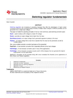
LTC3824 – High Voltage Step-Down Controller With 40µA ...
www.analog.comtime. The switching frequency can be programmed up to 600kHz and is easily synchronizable. Other features include current limit, soft-start, micropower shutdown, and Burst Mode disable. The LTC3824 is available in a 10-lead MSE power package. 5V/2A Buck Converter n Wide Input Range: 4V to 60V n Current Mode Constant Frequency PWM
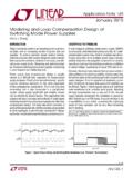
Switching regulator fundamentals (Rev. C)
www.ti.comON time of the switch. 2 Switching Converter Topologies The most commonly used DC/DC converter circuits will now be presented along with the basic principles of operation. 2.1 Buck Regulator The most commonly used switching converter is the Buck, which is used to down-convert a DC voltage to a lower DC voltage of the same polarity.

DC to DC Converters
www.site.uottawa.caInverting Buck Boost Converter • The last and most important type of switching regulator is the buck-boost converter. In this converter, the buck and boost topologies covered earlier are combined into one. A buck-boost converter is also built using the same components used in the converters covered before. The inductor in this
AN149 Modeling and Loop Compensation Design of …
www.analog.comground in the buck converter. The common terminal “c” is connected to a current source, which is the inductor in the buck converter. To change the time-variant SMPS into a time-invariant system, the 3-terminal PWM cell averagemodelingmethod can be applied by changing the active switch Q to an aver-

ROHM Switching Regulator Solutions Synchronous Buck ...
fscdn.rohm.comROHM Switching Regulator Solutions Synchronous Buck Converter Controller BD9611MUV-EVK-001 Description Using a synchronous rectified step-down DC/DC converter IC BD9611MUV BD 9611MUV-EVK-001 evaluation board 15.0 V ~ output a 24 V input voltage 12.0 V. Provides 10.0A output current. Output current is possible with current settings by selecting

Datasheet - XLSEMI
www.xlsemi.comBuck constant current driver General Description The XL4301 is a 180KHz fixed frequency PWM buck (step-down) DC/DC converter, apable of driving a 2.5A load with high efficiency, low ripple and excellent line and Requiring a minimum regulator is simple to use and include frequency compensation and a
Buck Converter Design - Mouser
www.mouser.deSwitching MOSFET The buck converter is a hard-switched topology. The switching MOSFET has to resemble an ideal switch, i.e. being low ohmic and fast switching. As with the synchronous rectifier MOSFET, the FOM is setting limits to as far one can come to an ideal switch. For a buck converter switch, the following are major MOSFET selection ...