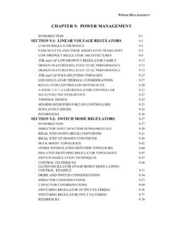
Transcription of DC TO DC CONVERTER CONTROLLER
1 DC TO DC CONVERTER CONTROLLER DESCRIPTION The MC34063 is a monolithic regulator subsystem, intended for use as DC to DC CONVERTER . This device contains a temperature compensated band gap reference, a duty-cycle control oscillator, driver and high current output switch. It can be used for step down, step-up or inverting switching regulators as well as for series pass regulators. FEATURES * Operation from to 40V. * Short circuit current limiting. * Low standby current . * Output switch current of without external transistors.
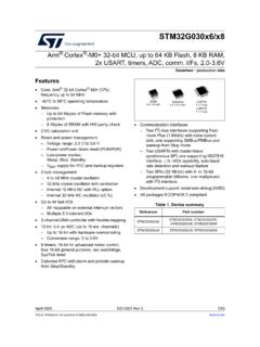
2 * Frequency of operation from 100Hz to 100kHz. * Step-up, step-down or inverting switch regulators. PIN CONFIGURATION PIN DESCRIPTION PIN NO PIN NAME I/O DESCRIPTION 1 Switch Collector I Internal Darlington pairs TI collector 2 Switch Emitter O Internal Darlington pairs TI emitter 3 Timing Capacitor The value of selected capacitor controls the internal oscillator run rate 4 GND 5 Comparator Inverting Input I Inverting input of comparator which can set & initiate the Darlington pairs output switch 6 VCC 7 IPEAK Sense I current sense input to monitor the
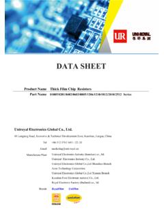
3 voltage drop across an external resistor placed in series with VCC 8 Driver Collector I Internal Darlington pairs TI collector DIP-8MC34063S SOP-8 BLOCK DIAGRAM 87542136 QSRCET1T2 AIsDBCTVccGNDT iming CapacitorSwitch EmitterSwitch InvertingInputIPEAK SenseDrive Collector ABSOLUTE MAXIMUM RATINGS (Ta=25 C ) PARAMETER SYMBOLRATINGS UNIT Supply voltage VCC 40 V Comparator Input voltage Range VIN(COMP) ~ +40 V Switch Collector voltage VC(SW)40 V Switch Emitter voltage VE(SW)40 V Switch Collector to Emitter voltage VCE(SW)
4 40 V Driver Collector voltage VC(DR) 40 V Switch current ISW A DIP-8 1250 Power Dissipation (Ta=25 C) SOP-8PD 625 mW Junction Temperature TJ +150 C Operating Temperature TOPR 0 ~ +70 C Storage Temperature TSTG -65 ~ +150 C Note: Absolute maximum ratings are those values beyond which the device which the device could be permanently damaged.
5 Absolute maximum ratings are stress ratings only and functional device operation is not implied. THERMAL DATA PARAMETER SYMBOLRATINGS UNIT DIP-8100 Junction-to-Ambient SOP-8 JA 160 C/W ELECTRICAL CHARACTERISTICS (VCC= , Ta=0~+70 C, unless otherwise specified.) PARAMETER SYMBOLTEST CONDITIONS MIN TYP MAX UNITO scillator Charging current ICHG VCC=5 to 40V, Ta=25 C 22 31 42 ADischarging current IDISCHG VCC=5 to 40V.
6 Ta=25 C 140 190 260 AOscillator Amplitude VOSC Ta=25 C V Discharge to Charge current Ratio K V7=VCC, Ta=25 C current limit Sense voltage VSENSE ICHG=IDISCHG, Ta=25 C 250 300 350mVOutput Switch Saturation voltage 1(Note) VCE(SAT)1 ISW= , VC(DRIVER)=VC(SW) Saturation voltage 2(Note) VCE(SAT)2 ISW= , VC(DRIVER)=50mA DC current Gain(Note) GI (DC) ISW= , VCE= , Ta=25 C 50 180 Collector Off State current (Note) IC(OFF)
7 VCE= , Ta=25 C 100 AComparator Threshold voltage VTHD Threshold voltage Line Regulation VTHD VCC=3 ~ 40V Bias current II(BIAS) VIN=0V 50 400nATotal Device Supply current ICC VCC=5~40V, CT= V7=VCC, VC>VTHD, Pin2=GND : Output switch tests are performed under pulsed conditions to minimize power dissipation.
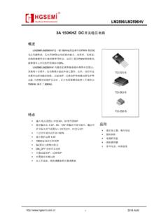
8 170 H1N58191808L1234CT765 RSC REF ++ +VOUT28V/175mA100+ HOptional Filter STEP-UP CONVERTER (Cont.) STEP-DOWN CONVERTER (Cont.) voltage INVERTING CONVERTER DESIGN FORMULA TABLE CALCULATION STEP-DOWN STEP-UP voltage -INVERTING tONtOFF VOUT + VF VIN-VCE(SAT) (tON+tOFF)MAX CT 4x10⁻⁵ tON 4x10⁻⁵ tON 4x10⁻⁵ tON ISW 2 IOUT(MAX) RS L(MIN) CO IOUT tONVRIPPLE(P-P) VCE(SAT)
9 - Saturation voltage of the output switch. VF - Forward voltage drop of the ringback rectifier. The following power supply characteristics must be chosen: VIN - Nominal input voltage . VOUT - Desired output voltage , VOUT = (1+R2/R1) IOUT - Desired output current . FMIN - Minimum desired output switching frequency at the selected values for VIN and IOUT. VRIPPLE(P-P) - Desired peak-to-peak output ripple voltage .
10 In practice, the calculated value will need to be increased due to the capacitor equivalent series resistance and board layout. The ripple voltage should be kept to a low value since it will directly effect the line and load regulation. TYPICAL CHARACTERISTICS