Transcription of ULN2003 LINEAR INTEGRATED CIRCUIT
1 UNISONIC TECHNOLOGIES CO., LTD ULN2003 LINEAR INTEGRATED CIRCUIT 1 of 10 Copyright 2018 Unisonic Technologies Co., Ltd 7CH darlington SINK DRIVER DESCRIPTION The UTC ULN2003 are high - voltage , high - current darlington drivers comprised of seven NPN darlington pairs. All units feature integral clamp diodes for switching inductive loads. Applications include relay, hammer, lamp and display (LED)drivers. FEATURES *Output current (Single Output): 500mA (Max.) * high Sustaining voltage Output: 50V (Min.) *Output Clamp Diodes *Inputs Compatible With Various Types Of Logic ORDERING INFORMATION Ordering Number Lead Free Halogen Free Package Packing ULN2003L-D16-T ULN2003G-D16-T DIP-16 Tube ULN2003L-S16-R ULN2003G-S16-R SOP-16 Tape Reel ULN2003L-P16-R ULN2003G-P16-R TSSOP-16 Tape Reel MARKING DIP-16
2 SOP-16 / TSSOP-16 ULN2003 LINEAR INTEGRATED CIRCUIT UNISONIC TECHNOLOGIES CO., LTD 2 of 10 PIN CONNECTION BLOCK DIAGRAM Note: The input and output parasitic diodes cannot be used as clamp diodes. ULN2003 LINEAR INTEGRATED CIRCUIT UNISONIC TECHNOLOGIES CO., LTD 3 of 10 ABSOLUTE MAXIMUM RATINGS (TA=25 C, unless otherwise specified)
3 PARAMETER SYMBOLRATING UNIT Output Sustaining voltage VOUT ~ 50 V Input voltage VIN ~ 30 V Clamp Diode Reverse voltage VR 50 V Output current IOUT 500 mA / chClamp Diode Forward current IF 500 mA DIP-16 W SOP-16 (Note2) W Power Dissipation TSSOP-16 PD W Junction Temperature TJ +150 C Operating Temperature TOPR -40 ~ +85 C Storage Temperature TSTG -55 ~ +150 C Notes: 1.
4 Absolute maximum ratings are those values beyond which the device could be permanently damaged. Absolute maximum ratings are stress ratings only and functional device operation is not implied. 2. On PCB (Test Board: JEDEC 2s2p) RECOMMENDED OPERATING CONDITIONS (TA=-40~+85 C, unless otherwise specified) CHARACTERISTIC SYMBOLTEST CONDITIONS MIN TYP MAXUNITO utput Sustaining voltage VOUT 0 50 V Duty=10% 0 350 DIP-16 Duty=50% 0 100 Duty=10% 0 300 SOP-16 Duty=50% 0 90 Duty=10% 0 150 Output current TSSOP-16 IOUT TPW = 25ms7 Circuits TA = 85 C TJ = 120 CDuty=50% 0 30 mA/chInput voltage VIN 0
5 24 V Input voltage (Output On) VIN (ON) IOUT = 400mA 24 V Input voltage (Output Off) VIN (OFF) 0 Clamp Diode Reverse voltage VR 50 V Clamp Diode Forward current IF 350mADIP-16 TA = 85 C TA = 85 C (Note) Dissipation TSSOP-16 PD TA = 85 C Note: On PCB (Test Board: JEDEC 2s2p) ULN2003 LINEAR INTEGRATED CIRCUIT UNISONIC TECHNOLOGIES CO., LTD 4 of 10 ELECTRICAL CHARACTERISTICS (TA=25 C, unless otherwise specified) CHARACTERISTIC SYMBOL TEST CIRCUITTEST CONDITIONS MIN TYP MAX UNITVCE=50V, TA=25 C 50 Output Leakage current ILEAK 1 VCE=50V, TA=85 C 100 AIOUT=350mA, IIN=500 A , IIN=350 A Saturation voltage VCEO(SAT)
6 2 IOUT=100mA, IIN=250 A DC current Transfer Ratio hFE 2 VCE=2V, IOUT=350mA 1000 Input current (Output On) IIN (ON) 3 VIN= , IOUT=350mA current (Output Off) IIN (OFF) 4 IOUT=500 A, TA=85 C 50 65 AIOUT = 350 mA voltage (Output On) VIN(ON) 5 VCE=2V IOUT = 200 mA VR=50V, TA=25 C 50 Clamp Diode Reverse current IR 6 VR=50V.
7 TA=85 C 100 AClamp Diode Forward voltage VF 7 IF=350mA Input Capacitance CIN 15 pFTurn-On Delay tON 8 VOUT=50V, RL=125 CL=15pF Turn-Off Delay tOFF 8 VOUT=50V, RL=125 CL=15pF sULN2003 LINEAR INTEGRATED CIRCUIT UNISONIC TECHNOLOGIES CO.
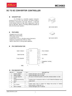
8 , LTD 5 of 10 TEST CIRCUIT Components in the test circuits are used only to obtain and confirm the device characteristics. These components and circuits are not guaranteed to prevent malfunction or failure from occurring in the application equipment. ULN2003 LINEAR INTEGRATED CIRCUIT UNISONIC TECHNOLOGIES CO., LTD 6 of 10 TEST CIRCUIT (Cont.) OPENOPENVFIF7. VFNote 1: Pulse width 50 s ,duty cycle 10% Output impedance 50 tR 5ns, tF 10nsNote 2: See belowNote 3: CL includes probe and jig capacitanceTYPE NUMBERULN2003R10 VIH3 VINPUT CONDITION8.
9 TON, tOFFPULSEGENERATORNote 2 INPUTOPENVOUTRLCL=15pF(Note 3)(Note 1)OUTPUTINPUTOUTPUT50 TONTOFF905010905010tRtF50 sVIH0 VOLVOH50 ULN2003 LINEAR INTEGRATED CIRCUIT UNISONIC TECHNOLOGIES CO., LTD 7 of 10 APPLICATION NOTES This UTC ULN2003 has no protection functions for over- current and over- voltage . If the applied situation includes over- current or over- voltage , this IC may be destroyed. We should take care of the systems design with this IC. The OUTPUT, COMMON and GND lines should be designed carefully because the IC may be destroyed due to short- CIRCUIT between outputs, air contamination fault, or fault by improper grounding.
10 The UTC ULN2003 is a darlington driver array. When it is applied with a general logic CIRCUIT such as TTL or CMOS, resistors should be connected in series to every input to achieve a stable input current . When the load is connected between the output and the power supply, the COMMON pin should be shorted to the power supply to protect the IC from extra swing voltage . NOTICE ON PRODUCT USE (1) The absolute maximum ratings should be not exceeded, even for a moment, otherwise the device may be breakdown, damaged or deteriorated, and even injury by explosion or combustion. (2) The power supply fuse should be used to prevent a continuous large current from the over current situation and IC failure.