Transcription of UNISONIC TECHNOLOGIES CO., LTD
1 UNISONIC TECHNOLOGIES CO., LTD TDA7377 LINEAR INTEGRATED circuit 1 of 10 Copyright 2012 UNISONIC TECHNOLOGIES Co., Ltd 2 x 30W DUAL/QUAD POWER AMPLIFIER FOR CAR RADIO DESCRIPTION The UTC TDA7377 is a class AB car radio amplifier for car radio, it can work either in dual bridge or quad single ended configuration. The exclusive fully complementary structure of theoutput stage and the internally fixed gain guarantees the highest possible power performances with few external components.
2 Theon-board clip detector simplifies gain compression operation. The fault diagnostics makes it possible to detect mistakes during car radio set assembly and wiring in the car. FEATURES * High Output f=1 KHz RL=4 : 2 x 35W Max. 2 x 20W@THD= 10% 4 x 6 W @10% 4 x 10W / 2 @10% 2 x 30W / EIAJ@ VCC = RL=4 * CMOS Compatible Stand-by Function (Low ICC) * No Audible pop During st-by Operations * Internally Fixed Gain (26dB BTL and 20dB single ended) * No Bootstrap Capacitors and boucherot Cells * Diagnostics Facility on pin10 when output Clipping, shorted to Vcc or GND, thermal shutdown and soft short at turn on.
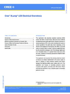
3 * Rail to rail output swing * Absolute Stability Without Any External Compensation. HZIP-15 DHZIP-15A PROTECTIONS * Load Dump Voltages surge * Reversed Battery * Output DC Short circuit protecttion with Low current when shorted to GND or VCC.* Output AC short circuit protection: across the load * Silent Turn On/Off * thermal shutdown * Load very Inductive speakers * Fortuitous Open GND * ESD ORDERING INFORMATION Ordering Number Package Packing Lead Free Halogen Free TDA7377L-J15-A-T TDA7377G-J15-A-T HZIP-15A Tube TDA7377L-J15-D-T TDA7377G-J15-D-T HZIP-15D Tube
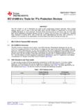
4 TDA7377L-J15-A-T(1) Packing Type(2) Package Type(3) Lead Free(1) T: Tube(2) J15-A:HZIP-15A, J15-D: HZIP-15D(3) L: Lead Free, G: Halogen Free TDA7377 LINEAR INTEGRATED circuit UNISONIC TECHNOLOGIES CO., LTD 2 of 10 PIN CONNECTION 151413121110987654321 OUT 3 OUT 4 VCCINPUT 3 INPUT 4 DIAGNOSTICSS-GNDPW-GNDSTAND-BYSVRINPUT 2 INPUT 1 VCCOUT 2 OUT 1 HZIP-15A TDA7377 LINEAR INTEGRATED circuit UNISONIC TECHNOLOGIES CO.
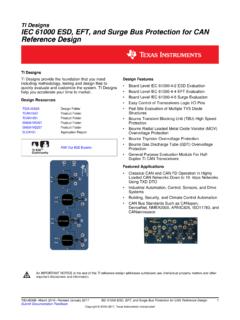
5 , LTD 3 of 10 BLOCK DIAGRAM 215141098611125741331 VCCVCCIN 1ST - BYIN 2IN 3IN 4PW - GNDSVRS - GNDOUT 2 OUT 1 OUT 3 OUT 4 DIAGNOSTICS+-+-+-+-A3A2 1 NVA4 1 NVA1 TDA7377 LINEAR INTEGRATED circuit UNISONIC TECHNOLOGIES CO., LTD 4 of 10 ABSOLUTE MAXIMUM RATINGS PARAMETER SYMBOL RATINGS UNIT Operating Supply Voltage VOP 18 V DC Supply Voltage VS 28 V
6 Peak Supply Voltage (for t = 50ms) VS(PEAK) 50 V Output Peak Current not Repetitive t = 100 sIO(PEAK) A Repetitive f >10Hz A Power Dissipation (TC= 70 C) HZIP-15A PD 33 W HZIP-15D 30 Junction Temperature TJ +150 C Storage Temperature TSTG -40~+150 C Note.
7 Absolute maximum ratings are those values beyond which the device could be permanently damaged. Absolute maximum ratings are stress ratings only and functional device operation is not implied. THERMAL DATA PARAMETER SYMBOL RATINGS UNIT Junction to Case HZIP-15A JC C/W HZIP-15D TDA7377 LINEAR INTEGRATED circuit UNISONIC TECHNOLOGIES
8 CO., LTD 5 of 10 ELECTRICAL CHARACTERISTICS (VS = ; RL = 4 ; f = 1 KHz; TA=25 C, unless otherwise specified) PARAMETER SYMBOL TEST CONDITIONS MIN TYP MAXUNITS upply Voltage Range VS 8 18 V ST-BY Threshold Voltage IN VI(ST-BY) V OUT VO(ST-BY) Voltage Saturation on pin 10 VSAT Sink Current at Pin 10 = 1mA V Output Offset Voltage VO(OFF) 150 mVInput Noise Voltage eN Rg = 0.
9 A weighted, Non Inverting Channels 2 V Inverting Channels 5 Bridge, Rg = 0; 22Hz ~ 22 KHz V Total Quiescent Drain Current IQ RL = 150 mAST-BY Pin Current(pin 7)
10 IST-BY Max Driving Current Under Fault 5 mAPlay Mode Vpin7 = 5V 50 A ST-BY Current Consumption IST-BY VST-BY = 0 ~ 100 A Clipping Detector Output Average Current OFF ICD(OFF) d = 1% (Note 2) 90 A ON ICD(ON) d = 5% (Note 2) 160 A Input Impedance RIN Single Ended 20 30 K Bridge 10 15 Output Power POUT THD = 10%.