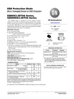
Transcription of Very low capacitance ESD protection - st.com
1 October 2011 Doc ID 11265 Rev 51/1414 USBLC6-2 Very low capacitance ESD protectionFeatures 2 data-line protection Protects VBUS Very low capacitance : pF max. Very low leakage current: 150 nA max. SOT-666 and SOT23-6L packages RoHS compliantBenefits Very low capacitance between lines to GND for optimized data integrity and speed Low PCB space consumption: mm2 max for SOT-666 and 9 mm max for SOT23-6L Enhanced esd protection : IEC 61000-4-2 level 4 compliance guaranteed at device level, hence greater immunity at system level esd protection of VBUS High reliability offered by monolithic integration Low leakage current for longer operation of battery powered devices Fast response time Consistent D+ / D- signal balance: Very low capacitance matching toleranceI/O to GND = pF Compliant with USB requirementsComplies with the following standards: IEC 61000-4-2 level 4: 15 kV (air discharge) 8 kV (contact discharge)Figure diagram (top view)Applications USB ports up to 480 Mb/s (high speed) Compatible with USB low and full speed Ethernet port.
2 10/100 Mb/s SIM card protection Video line protection Portable electronicsDescriptionThe USBLC6-2SC6 and USBLC6-2P6 are monolithic application specific devices dedicated to esd protection of high speed interfaces, such as USB , Ethernet links and video very low line capacitance secures a high level of signal integrity without compromising in protecting sensitive chips against the most stringently characterized ESD ID 11265 Rev 51 Characteristics Table ratingsSymbolParameterValueUnitVPPPeak pulse voltageIEC 61000-4-2 air dischargeIEC 61000-4-2 contact dischargeMIL STD883G-Method 3015-7151525kVTstgStorage temperature range-55 to +150 CTjOperating junction temperature range-40 to +125 CTLLead solder temperature (10 seconds duration)260 CTable characteristics (Tamb = 25 C)SymbolParameterTest currentVRM = V10150nAVBRB reakdown voltage between VBUS and GNDIR = 1 mA6 VVFF orward voltageIF = 10 voltageIPP = 1 A, 8/20 sAny I/O pin to GND12 VIPP = 5 A, 8/20 sAny I/O pin to GND17 VCi/o-GNDC apacitance between I/O and GNDVR = between I/OVR = Ci/o- ID 11265 Rev 53/14 Figure versus voltage (typical values)Figure capacitance versus frequency (typical values) (pF)F=1 MHzV=30mVT =25 COSCRMSjC =I/O-I/OjC =I/O-GNDOData line voltage (V) (pF)V=30mVT =25 COSCRMSjV=0V to (MHz)Figure variation of leakage current versus junction temperature (typical values)Figure response110100255075100125T ( C)jV=5 VBUSI[TRM j] / I[TRM j=25 C] (dB)F(Hz)
3 Technical informationUSBLC6-24/14 Doc ID 11265 Rev 52 Technical surge protectionThe USBLC6-2 is particularly optimized to perform surge protection based on the rail to rail clamping voltage VCL can be calculated as follow:VCL+ = VTRANSIL + VF for positive surgesVCL- = - VF for negative surgeswith: VF = VT + (VF forward drop voltage) / (VT forward drop threshold voltage)and VTRANSIL = VBR + exampleWe assume that the value of the dynamic resistance of the clamping diode is typically:Rd = and VT = VWe assume that the value of the dynamic resistance of the transil diode is typically:Rd_TRANSIL = and VBR = VFor an IEC 61000-4-2 surge Level 4 (Contact Discharge: Vg = 8 kV, Rg = 330 ), VBUS = +5 V, and if in first approximation, we assume that: Ip = Vg / Rg = 24 , we find:VCL+ = + VVCL- = -13 VNote:The calculations do not take into account phenomena due to parasitic surge protection application exampleIf we consider that the connections from the pin VBUS to VCC, from I/O to data line and from GND to PCB GND plane are done by tracks of 10 mm long and mm large, we assume that the parasitic inductances LVBUS, LI/O and LGND of these tracks are about 6 nH.
4 So when an IEC 61000-4-2 surge occurs on data line, due to the rise time of this spike (tr=1ns), the voltage VCL has an extra value equal to + dI/dt is calculated as:dI/dt = Ip/tr = 24 A/nsThe overvoltage due to the parasitic inductances is: = = 6 nH x 24 A/ns = 144 VBy taking into account the effect of these parasitic inductances due to unsuitable layout, the clamping voltage will be:VCL+ = + + 144 + 144 = VVCL- = - 144 - 144 = VUSBLC6-2 Technical informationDoc ID 11265 Rev 55/14We can significantly reduce this phenomena with simple layout optimization. It is for this reason that some recommendations have to be followed (see : How to ensure good esd protection ).Figure behavior: parasitic phenomena due to unsuitable How to ensure good ESD protectionWhile the USBLC6-2 provides high immunity to ESD surge , efficient protection depends on the layout of the board.
5 In the same way, with the rail to rail topology, the track from data lines to I/O pins, from VCC to VBUS pin and from GND plane to GND pin must be as short as possible to avoid overvoltages due to parasitic phenomena (see Figure 6. and Figure 7. for layout consideration) VBUSLI/OLVBUSLGNDLI/OLGNDVpinCCVCLVFI/O pinVTRANSILV+VTRANSILF-VFVCL-t = 1 nsrttt = 1 nsrVCL+GND pinData linePositiveSurgeNegativeSurgeESD surge on data linedidtLI/O+ LGND didtdidt-LI/O- LGND didtdidtV+=V+V + L+ Lsurge > 0 CLTRANSILFI/OGNDV= -V - L- Lsurge > 0CL- +=Figure behavior: layout optimizationFigure behavior: measurement conditionsUnsuitable layoutOptimized layout11625341162534+5 VINOUTTEST BOARDESD SURGEUSBLC6-2SC6 Technical informationUSBLC6-26/14 Doc ID 11265 Rev 5 Important:A good precaution to take is to put the protection device as close as possible to the disturbance source (generally the connector).
6 Crosstalk Crosstalk phenomenonFigure 11. Crosstalk phenomenonThe crosstalk phenomenon is due to the coupling between 2 lines. The coupling factor ( 12 or 21) increases when the gap across lines decreases, particularly in silicon dice. In the above example the expected signal on load RL2 is 2VG2, in fact the real voltage at this point has got an extra value 21VG1. This part of the VG1 signal represents the effect of the crosstalk phenomenon of the line 1 on the line 2. This phenomenon has to be taken into account when the drivers impose fast digital data or high frequency analog signals in the disturbing line. The perturbed line will be more affected if it works with low voltage signal or high load impedance (few k ).Figure response to IEC 61000-4-2 (+15 kV air discharge)Figure 10. ESD response to IEC 61000-4-2 (-15 kV air discharge)VinVoutVinVoutLine 1 Line 2VG1VG2RG1RG2 DRIVERSRL1RL2 RECEIVERS +112VG1VG2 +221VG2VG1 USBLC6-2 Technical informationDoc ID 11265 Rev 57/14 Figure 12.
7 Analog crosstalk measurementsFigure 12. shows the measurement circuit for the analog application. In usual frequency range of analog signals (up to 240 MHz) the effect on disturbed line is less than -55 dB (see Figure 13.).Figure 13. Analog crosstalk resultsAs the USBLC6-2 is designed to protect high speed data lines, it must ensure a good transmission of operating signals. The frequency response (Figure 5.) gives attenuation information and shows that the USBLC6-2 is well suitable for data line transmission up to 480 Mbit/s while it works as a filter for undesirable signals like GSM (900 MHz) frequencies, for ANALYSERPORT 2 NETWORK ANALYSERPORT 1 TEST (Hz)Technical informationUSBLC6-28/14 Doc ID 11265 Rev Application examplesFigure 14. USB port application diagram using USBLC6-2 Figure 15. T1/E1/Ethernet protectionHUB-DOWNSTREAMTRANSCEIVER+ 5 VRSRSRSRSRPDRPDRPDRPDP rotectingBus SwitchDEVICE-UPSTREAMTRANSCEIVER+ +D-GNDVBUSVBUSVBUSRX LS/FS+RX LS/FS+RX LS/FS+RX LS/FS+RX HS+RX HS+RX HS+RX HS+TX HS+TX HS+TX HS+TX HS+TX LS/FS+TX LS/FS+TX LS/FS+TX LS/FS+RSRSUSB connectorTX LS/FS -TX LS/FS -TX LS/FS -TX LS/FS -RX LS/FS -RX LS/FS -RX LS/FS -RX LS/FS -RX HS -RX HS -RX HS -RX HS -TX HS -TX HS -TX HS -TX HS -GNDGNDGNDGNDSW2 DEVICE-UPSTREAMTRANSCEIVERUSBLC6-4SC6 USBLC6-2P6 USBLC6-2SC6+ +D-GNDRSRSUSB connectorSW2 OpenClosed then openHigh Speed HSOpenClosedFull Speed FSClosedOpenLow Speed LSSW2SW1 ModeDATATRANSCEIVERSMP75-8 SMP75-8 TxRx+VCC+VCC100nF100nFUSBLC6-2SC6 USBLC6-2SC6 USBLC6-2 Technical informationDoc ID 11265 Rev 59 PSpice modelFigure 16.
8 Shows the PSpice model of one USBLC6-2 cell. In this model, the diodes are defined by the PSpice parameters given in Figure 16. PSpice modelNote:This simulation model is available only for an ambient temperature of 27 C. MODEL = DlowMODEL = DhighVBUSLI/OLGNDGNDD+inMODEL = DzenerRI/OLI/OD-inRI/OLI/OLI/ORGNDRI/OD- outRI/OMODEL = DlowMODEL = DhighLI/OD+outRI/OFigure 17. PSpice parametersFigure 18. USBLC6-2 PCB layout +inD+outD-outGNDUSBLC6-2D-inVBUS1C= 100nFBUSO rdering information schemeUSBLC6-210/14 Doc ID 11265 Rev 53 Ordering information schemeFigure 19. Ordering information schemeUSB LC 6 - 2 xxxProduct DesignationLow capacitanceBreakdown VoltagePackages6 = 6 Volts2 = 2 linesSC6 = SOT23-6LP6 = SOT-666 Number of lines protectedUSBLC6-2 Package informationDoc ID 11265 Rev 511/144 Package information Epoxy meets UL94, V0 Lead-free packagesIn order to meet environmental requirements, ST offers these devices in different grades of ECOPACK packages, depending on their level of environmental compliance.
9 ECOPACK specifications, grade definitions and product status are available at: ECOPACK is an ST trademark. Table 20. SOT-666 footprintdimensions in mmFigure 21. SOT-666 informationUSBLC6-212/14 Doc ID 11265 Rev 5 Table Max. 0 10 0 10 A2 ALHcbEDeeA1qFigure 22. SOT23-6L footprint dimensions in mmFigure 23. SOT23-6L informationDoc ID 11265 Rev 513/145 Ordering information 6 Revision history Table informationOrder codeMarkingPackageWeightBase qtyDelivery mg3000 Tape and mg3000 Tape and reelTable revision historyDateRevisionChanges14-Mar-20051 First change to figure 3; no content marking illustrations - Figures 21 and 23. Added ECOPACK statement. Updated operating junction temperature range in absolute ratings, page 2.
10 Technical information section updated. Reformatted to current leakage current for VRM = V as specified in USB standard. Updated marking illustrations Figure 21 and Figure legal ID 11265 Rev 5 Please Read Carefully:Information in this document is provided solely in connection with ST products. STMicroelectronics NV and its subsidiaries ( ST ) reserve theright to make changes, corrections, modifications or improvements, to this document, and the products and services described herein at anytime, without ST products are sold pursuant to ST s terms and conditions of are solely responsible for the choice, selection and use of the ST products and services described herein, and ST assumes noliability whatsoever relating to the choice, selection or use of the ST products and services described license, express or implied, by estoppel or otherwise, to any intellectual property rights is granted under this document.