Transcription of DEMOUNTING AND MOUNTING PROCEDURES …
1 1. Beforeinflatinganytirerim/wheelassembly, be sure to read, understand and complywith ALL , be certain that the side or lock ring is MOUNTING the tire on the rim, PlacetheassemblyinanOSHA-compliantrestra iningdevice, such as a tire safety 5A is an example of a portable device. Man-ufacturers recommend that restraining devices befreestanding and located at least one foot awayfrom any flat or solid Inflatethetire,withthevalvecoreremoved,u sing a clip-on air chuck with an in-line valve orpressure regulator and a sufficient length of restraining device. For tube-type tires, the tire can be deflated after reach-ing 20 psi and re-inflated to prevent inner !Look for distortions, undulations,orotherirregularitiesintheti residewall,suchasinPhoto 5B. Listen for any popping or snappingsounds. If ANY of these conditions are present STOP!DONOT approach tire. Before removingfrom restraining device, completely deflate tire re-motely. Remove clip-on air chuck. Mark tire asdamaged for potential zipper rupture.
2 Render tire unservicable, non-repairable and Visuallyinspectmulti-piecetirerim/wheela ssembliesthroughout the inflationprocessfor improperseating of the ringsand/orbeads. Wheninflating atire,stay out of the tra-jectory.(See Trajectory Warningbelow.)DONOT standorleananypartofyourbodyagainst,or reach over, the restraining device during both sides ofthe tire to be sure that the beads are evenly beyond 40 psi to seat anytire beads. If the beads are not seated at 40 psi STOP!Completely deflate, remove from therestraining device, and determine the problem. Reposition the tire and/or inner tube on therim, relubricate, and Afterthetirebeadsareseated,continuetoinf latethetireto its recommended infla-tion !Look for distortions, undulations, or other irregularities in the tire sidewall,such as in Photo 5B. Listen for any popping or snapping sounds. If ANY of these conditions arepresent STOP! ,completelydeflate tire clip-on as damaged for potential zipper rup-ture.
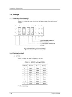
3 Render tire unservicable, non-repairable and none of these zipper conditions are present,removeclip-onairchuck,installthe valvecore,andadjusttheinflationpressuret o the recommended operating Beforeremovingthe tire rim/wheel assembly from the restraining device, always visuallyinspect for proper seating of the beads and all for air leaks. Install a suitable valve PRODUCTION: TWO-PIECE SOLID RIM; SPLIT RING - LW, sure the top bead is unseated and below the side ring before at-tempting to remove it. Insert the tapered end of the lock ring tool intothe notch and pry the side ring out of the rim gutter. Lift wheel to remove the side ring by progressively prying around therim. Use small bites to prevent distorting the side a tire stand on the rim. Turn the assembly over. Unseat the bot-tom bead. Remove the tire from the rim. Remove the tube and flapfrom the PRODUCTION: THREE-PIECE SOLID RIM; SPLIT LOCK RING;SOLID FLANGE-M, CR, 5 sure the top bead is unseated and the flange is below the lockring before attempting to remove the lock ring.
4 Insert the tapered endof the lock ring tool into the notch and pry the lock ring out of the rimgutter. Lift wheel from the lock ring tool between the lock ring and the flange. Removethe lock ring by progressively prying around the rim. Use small bitesto prevent distorting the lock ring. Remove solid a tire stand on the rim. Turn the assembly over. Unseat the bot-tom bead. Remove the tire from the rim. Remove the tube and flapfrom the *: SPLIT RIM; SOLID sure the top bead is unseated and insert the tapered end of thelock ring tool into the notch in the rim near the split. Push the tooldownward and toward the center of the rim. A block of wood may beplaced under the left side of the rim split to help offset the rim the tapered end of the lock ring tool into the second notch andpush downward toward the center of the rim, prying the solid sidering from the rim. Remove the solid side a tire stand on the rim. Turn the assembly over. Unseat the bot-tom bead.
5 Remove the tire from the rim. Remove the tube and flapfrom the *: SOLID RIM; SOLID RING-RH; 5 sure the top bead is unseated and insert the tapered end of thelock ring tool into the notch in the solid side ring. This notch is lo-cated between the embossments on the solid side lock ring tool handle downward to pry the solid side ring from therim. Continue prying around the rim until the solid side ring is the solid side ring from the rim. Turn the assembly over * NOTE:Theserims are no longer in production and replacement parts are YOU DO NOT KNOW HOW TO USE TIRE SERVICING TOOLS STOP!TIRE SERVICING MUST ONLY BE PERFORMED BY TRAINED TO FOLLOW PROPER PROCEDURES CAN RESULT IN SERIOUS INJURY OR SERVICING ANY TIRE RIM/WHEEL ASSEMBLYMOUNTING TIRE ON RIM/WHEEL ASSEMBLY AALLWWAAYYSScom ply with the procedureson this chart and in thetire/wheel manufacturer's catalogs, instruction manuals or otherindustry and government instructional materials. Before loosening any nuts or clampsthat attach a tube-typetire/rimassembly to a vehicle, ALWAYS completely deflate the tire (or bothtires of a dual assembly) by taking out the valve core(s).
6 Use a non-flammable vegetable or soap-based rubber lubricanton the beads and rim surfaces to make tire DEMOUNTING andmounting easier. Use proper tools to demount or mount tires and rims(refer to Typ-ical Tire Service Tools ). NEVERuse a steel hammer to seat rim com-ponents use only rubber, plastic or brass-tipped mallets. Striking arim/wheel assembly with a hard-faced hammer can damage thecomponents and endanger the installer. Use a steel duck bill hammeronly as a wedge to unseat the beads of tube-type tires. NEVER strikethe tire/wheel assembly with a steel duck bill hammer to unseat thebeads and do not strike the head of the duck bill hammer with an-other hard-faced hammer use a rubber mallet or plastic dead blowhammer. Slide impact tools and hydraulic bead unseating tools canalso be used to unseat beads on tube-type tires. NEVER reinflate any tire that has been operated in a run-flat orunderinflated condition( , operated at 80% or less of recom-mended operating pressure).
7 Demount, inspect and match all tireand rim components before reinflating in a restraining device withthe valve core E M O U N T I N G A N D M O U N T I N G P R O C E D U R E S D E M OU N T I N G A N D M O U N T I N G P R O C E D U R E S F O R TU B E - T Y P E T R U C K A N D B U S T I R E SF O R TU B E - T Y P E T R U C K A N D B U S T I R E STIRE AND RIM SERVICING CAN BE DANGEROUS AND MUST ONLY BE PERFORMED BY TRAINED PERSONNEL USING PROPER PROCEDURES AND TOOLS. FAILURE TO READ AND COMPLY WITH ALL OF THESE PROCEDURES MAY RESULT IN SERIOUS INJURY OR DEATH TO YOU AND deflate any tire by removingthe valve core before removing thetire/wheel assembly from the axle if thereis known or suspected damage to the tire orwheel or if the tire has been operated at80% or less of its recommended operatingpressure. Demount, inspect and match alltire and rim parts before re-inflating in a re-straining starter fluid, ether, gasoline,or other flammable materials and/or accel-erants to lubricate the beads of a tire.
8 Thispractice can cause the explosive separationof the tire/wheel during servicing or duringhighway use, which may result in serious in-jury or beyond 40 psi to seat anytire beads. NEVER stand, lean, or reach overthe tire rim/wheel assembly in the restrain-ing device during inflation. Even if a tire is ina restraining device, inflating beyond 40 psiwhen trying to seat the beads is a DANGER-OUS PRACTICE that may break a tire beador the rim/wheel with explosive force andpossibly result in serious injury or death. Any inflated tire mounted on a wheel con-tains explosive energy. The use of damaged,mismatched or improperly assembled tireand wheel components can cause the as-sembly to separate with explosive force. Ifstruck by an exploding tire, wheel compo-nent, or the air blast, you or someone elsemay be seriously injured or and inflation of mismatchedcomponents on multi-piece tire and wheelassemblies can result in serious injury ordeath. Just because the components comein or fit together does not mean they arematched.
9 Check the identification stampsfor proper matching of all rim parts beforeassembling a multi-piece tire and tire and rim diameters isdangerous. A mismatched tire and rim as-sembly may separate and can result in seri-ous injury or death. This warning applies to15 and , 16 and , 18 , 22 and , 24 and tire andrim assemblies as well as other sized a tire and rimunless you have positively identified and cor-rectly matched the tire and rim diameter. ALWAYS wear adequate protective eyewear (orface shield), protective footwear, and ear pro-tection while servicing tires to avoid injury. NEVERuse a tire tool for anything except de- MOUNTING and MOUNTING tires. NEVERuse an extension or cheater bar withtire irons. ALWAYSuse soft-faced hammers when drivingtire irons or assembling components. NEVERuse a hammer with a loose or crackedhandle. NEVERuse a bent, cracked, chipped, dented ormushroomed tool. Keep tools clean and in-spect them frequently.
10 NEVER alter or apply heat to any tire servicetool. DEFLATING AND DEMOUNTING TIRE FROM RIM/WHEEL ASSEMBLYINFLATING TIRE RIM/WHEEL ASSEMBLY11 ALWAYS conduct a visual and tactile inspection of the tire,rim/wheel and its components. LOOKand FEELfor any damage or evi-dence of being operated overloadedand/or in a run-flat condition (80% or lessof its recommended operating inflationpressure).Photo 3A is an example of innerliner damage created by an un-derinflated and overloaded tires that have undulationsor irregular sidewall distortions could possibly havepermanent sidewall structural damage (steel cordfatigue). Ply cords weakened by underinflationand/or overloading may break one after another,until a rupture occurs in the upper sidewall with ac-companying instantaneous air loss and explosiveforce. This can result in serious injury or death. Fol-low tire industry recommended inspection PROCEDURES for tires with these charac-teristics.