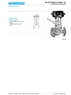
Transcription of DENISON HYDRAULICS VENUS Controller 020-14103
1 Publ. 9-AM651-ADENISON HYDRAULICSVENUS Controller020-14103 Internet: : CHARACTERISTICSThe Absolute Maximum ratingsare for reference only. Operatingthis device in these regions maycause this unit to Width Modulation (PWM) withcurrent feedback and short circuit MaximumPower Supply12-24 VDC34 VDC@ Amps + coil currentLocal Command Set Digitally-100% - +100%Main input Commands 10 VDC 50 VDC 5 VDC 50 VDC 0-20mA 30mA DC4-20mA+30mA DCAuxiliary Input Command 5 VDC 50 VDCA nalog Feedback Inputs 10 VDC 50 VDC 5 VDC 50 VDC 0-20mA 30mA DC4-20mA+30mA DCHorsepower Limiting Inputs0-1 Amp AC2 Amps AC continuous4-20mA DC+30mA DC0-10V DC 50 VDCD ifferential Encoder Inputs5 VDC 15 VDCS ingle Ended Encoder Inputs5 VDC 25 VDCM agnetic Pickup97mVAC RMS70 VAC RMSP roximity Probe5 VDC 25 VDCD igital FeedbackFrequency Range21 - 100.
2 000 HzEmergency Stop12 - 24 VDC 50 VDCR everse CMD12 - 24 VDC 50 VDCSoft Stop12 - 24 VDC 50 VDCRamp 1 / Ramp 212 - 24 VDC 50 VDCMain / Aux Command12 - 24 VDC 50 VDCO utput Driver Current Ranges Frequency Ranges100Hz140Hz200Hz2000 HzEncoder Excitation5 VDC30mADCP otentiometer Excitation+5 VDC10mADC-5 VDC10mADCRamp 1 & Ramp 2 Set with Terminal S20-141250-90 SecondsSet with PC Program S20-141310-300 SecondsSoft StopActivated ramp rate0-60 SecondsDe-activated ramp rate0-60 SecondsOperating Temperature0oto 70oCUser InterfaceRS232 9 pin FemaleD type connectorDIN RAIL Mounting35mm x x 15mmDimensions, in. (mm) (110) (149) (75) DDATA2 RevisedNote:New revisions are shown are marked revisedwhere changes have been :The chassis GND, terminal 24, isconnected to the internal shieldand must be connected to anEarth / Safety Ground for properdevice Emergency Stop input, termi-nal 27, must be connected to 12-24 VDC to allow VENUS outputsto 27 and 32 are isolatedand require a Ground (GND)
3 Reference to operate drawing shows the output terminals are config-ured such that with a positive inputcommand Coil A will be HARDWARE REQUIREMENTSCOIL A3738 COIL B363524252627282930313233343536373839401 2-24 VDCPOWERMOTOR+A-A+B -B9 ASTROKER+V-VCHASSISGNDEMERGENCY STOPJ1 ISOLATED GNDJUMPERGETTING STARTED3 INSTALLATION GUIDELINES4 RevisedALWAYSNEVERWHEREVER POSSIBLElRead this data sheet completely this Controller and any electronic control device in an electrically conductivemetal the enclosure to an ELECTRICALLY CLEAN Earth Ground with a mini-mum wire size of 12 High Voltage AC power lines seperate from Low Voltage DC control signals,current loops, feedback signals (voltage, current and frequency types) and shielded cable for all control signals, feedback signals and coil all shields to the enclosure for proper termination and leave the other endof the shield terminal #24 on the Controller to the enclosure for proper all connections to and from the Controller to ensure correct connections andtightness of the that the supply voltage is correct.
4 ELECTRICALLY CLEAN and DENISON HYDRAULICS if unsure of attempt to use this unit if you are unsure of the connections or use a power supply that is marginal or under rated for the current require-ments of the coil being use this unit in areas of intense RF radiation without adequate shielding this unit powered and use the Emergency Stop or Soft Stop inputs to turnoff the outputs when the hydraulic system is not METHODS5 RevisedThe Controller can communicate to theuser by two different 1 METHOD 2l286 - based computer (with 640K RAM).If running Windows (with 4M RAM)If running Microsoft Windows 95 l486 or Pentium - based computer (with minimum 16M RAM).lVGA or SuperVGAC onfiguration Data StorageThe VENUS Controller requires configuration before the unit will function parameters must be programmed by the user to configure the Controller to 1:The hand held terminal, S20-14125, will prompt the user through a menusystem to setup VENUS .
5 No other programming tools are required. Refer to page 15for operating 2: A PC computer interface using the S20-14131 Interface program, VDOS,and a portable S20-14131 program is DOS based and is compatablewith Windows and Windows are several benefits to using this The control parameters can be entered and stored on disk, even when not connect-ed to the VENUS Multiple setup files can be saved to The configuration can be retrieved from VENUS for backup The same setup file can be used for multiple VENUS the VGRAPH program, the input command, feedback signal and error can be dis-played on the computer screen similar to that of a strip chart recorder. As the systemperformance is being displayed in real time, the tuning variables of Proportional Gain(Kp), Integrating Gain (Ki) and Integrating Rate (KIT) can be dynamically adjusted toget the optimum system configuration data is stored in a non-volatile memory card inside VENUS .
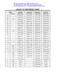
6 If the con-troller fails and needs to be replaced, the memory card can be removed from thedefective unit and inserted into the replacement unit configuring the new one exactlyas the HydraulicsS20-14131PC InterfaceSoftwarePOWER SUPPLYREQUIREMENTSI nputsDigital InputsEmergency stopMain input / Auxiliary input selectRamp 1 / Ramp 2 selectSoft stopReverse CommandHorse Power (HP) LimitingThe VENUS Controller requires 12-24 VDC to operate, the current requirements aredetermined by the type of actuator that is connected to VENUS . The following list shows the current requirements of the DENISON HYDRAULICS stroker 12V12 VDC at AMPS Minimum9 APump stroker 24V24 VDC at AMPS MinimumF5 CFlow control valve24 VDC at AMPS MinimumVP01 Pressure control valve24 VDC at AMPS Minimum4RP01 Pressure control valve 12V12 VDC at AMPS Minimum4RP01 Pressure control valve 24V24 VDC at AMPS Minimum3DP03 Open loop 24V24 VDC at AMPS Minimum3DP06 Open loop 12V12 VDC at AMPS Minimum3DP06 Open loop 24V24 VDC at AMPS Minimum4DP01 Open loop 12V12 VDC at AMPS Minimum4DP01 Open loop 24V24 VDC at AMPS Minimum4DP02 Open loop 12V12 VDC at AMPS MinimumNOTICE:12V coils MUST be powered by a 12V power supply.
7 Using a 24 Volts for12V coils may result in an over current shut down which may cause the power supplyoutput to brown out and reset commands can be voltages, current loops or potentiometers. Multiple inputs arepermitted and are selected by the Main / Auxiliary input. The input command can alsobe programmed internally as a LOCAL COMMANDset digitally using the S20-14125hand held terminal or with a PC computer using the S20-14131 devices can be incremental optical encodes, passive and active magneticpickups, DC tachometers, DC voltages or current loops, hydraulic flow meters, poten-tiometers, pressure, load and torque transducers, and current transformers for horsepower limiting.(12-24 VDC Isolated Inputs with isolated GND on terminal 32)Voltage must be applied to this input to enable the Controller s a voltage to terminal 28 will cause the Controller to accept the input com-mand from the Auxiliary input instead of the Main 1 is the default selection, applying a voltage to terminal 29 will select Ramp option is used to set the output to zero at the rate set by the Soft Stop Time.
8 Thisoption can be enabled or disabled through the system configuration. When enabled,terminal 30 must be energized to allow the system outputs to function. De-energizingterminal 30 will engage the soft stop function. When disabled, terminal 30 may be a voltage will cause the Controller to reverse the input command, with+5 VDC input command and coil A output energized the new input will become -5 VDCwhen reverse command is asserted and energize coil B output . VENUS can sense Horse Power in 1 of 2 ) Measure the electric motor ) Anti-stall - measure the prime mover s output shaft speed, diesel ) Electric Motor horsepower and electric motor current are directly related. HP ismeasured using a current transformer which is rated as a ratio of input current tooutput signal, 125:1, 125:20mA or 125:10 VDC meaning that for an input cur-rent of 125 AmpsAC the transformer output will be 1 AmpAC, 20mADC or output of the current transformer is fed into the VENUS Controller and com-pared to the adjustable limit.
9 When the measured HP exceeds the pre-set limit thecontroller will de-stroke the pump as a function of the HP Limit ) The prime mover s shaft speed, typically a diesel engine, is measured as a fre-quency and compared with the adjustable limit, as the HP requirements increasethe prime movers RPM decreases. When the shaft speed drops below the limit, VENUS will de-stroke the pump as a function of the HP Limit gain. VENUS has only1 frequency input, the user must decide which function it will serve, the systemfeedback or the HP GeneratorsOutputsHigh Level OutputsVenus has two independently adjustable ramps. Ramp 1, when selected (defaultramp), has adjustable up and down ramp times of to 90 seconds. Ramp 1 up andramp 1 down can be enabled or disabled independently, also Ramp 2, when selected (12 to 24 VDC applied to terminal 29) has its own up and downramp time adjustments of to 90 seconds and ramp 2 up and ramp 2 down can beindependently enabled or.
10 Using the S20-14131 PC interface program the Ramp 1 and Ramp 2 times to 300 ramp can be configured in one of two different types of ramp models as VENUS Controller has three outputs, one high current (coil A & coil B), one low volt-age and one low high current output stage is a two channel PWM driver with current feedback forprecise control of the current through the coil regardless of changes in coil channels are protected against short circuits across the coil and to following is a list of DENISON s hydraulic actuators that VENUS can control one of the following selections using the S20-14125 terminal or the S20-14131 PC software will automatically configure the Controller for the maximum currentand PWM frequency required by the stroker 12V or 24VF5 CFlow control valveVP01 Pressure control valve4RP01 Pressure control valve3DP03 Proportional directional valve (open loop) 12V or 24V3DP06 Proportional directional valve (open loop)