Transcription of DESCRIPTION TECHNICAL GUIDE - UPGNET
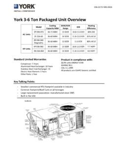
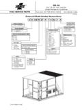
1 292458-YTG-A-0207 FOR DISTRIBUTION USE ONLY - NOT TO BE USED AT POINT OF RETAIL SALESINGLE PACKAGE GAS/ELECTRIC UNITSAND single PACKAGEAIR CONDITIONERSD(CE, CG) 036, 048, 060 & 0723, 4, 5 & 6 NOMINAL SEER (3, 4, & 5 Ton), EER (6 Ton) TECHNICAL GUIDEDESCRIPTIONYORK Sunline 2000 units are convertible single package air conditioners with a common cabinet and a common roof curb for the 3, 4, 5 and 6 ton sizes. The units were designed for light commercial and commercial applications. They can easily be installed on a roof curb, slab, roof jack or units include: Powder Paint finish that meets ASTM-B-117 1000 hour salt spray standards Permanently lubricated motors Bottom or side air discharge configuration capability (field convertible) Manufactured under the quality standards of ISO9001 Copper tube/aluminum fin coils Easy access to all components Rigging holes in base rails for lifting Fork lift slots on three sides single point power connection Complete factory package - tested, charged and wired CSA agency listing on all unitsWARRANTY Factory Limited Parts Warranty One-year parts warranty A Five-year parts warranty on the compressor andelectric heat elements.
2 Ten-year parts warranty on the gas-fired Products GroupTABLE OF CONTENTSDESCRIPTION .. 1 PRODUCT NOMENCLATURE .. 3 FEATURES .. 4 FACTORY-INSTALLED OPTIONS .. 5 FIELD-INSTALLED ACCESSORIES .. 5 GUIDE SPECIFICATIONS .. 39 LIST OF FIGURESFig. #Pg. #1 UNIT CUTAWAY .. 52 TYPICAL FIELD POWER & CONTROL WIRING .. 233 UNIT DIMENSIONS (3 - 6 TON COOLING ONLY/ELECTRIC HEAT) FRONT VIEW .. 244 UNIT DIMENSIONS (3 - 6 TON COOLING/GAS HEAT) FRONT VIEW .. 245 UNIT WITH ECONOMIZER RAINHOOD .. 256 UNIT WITH FIXED OUTDOOR AIR/MOTORIZED DAMPER RAINHOOD .. 257 UNIT DIMENSIONS (REAR VIEW) .. 268 DISCONNECT/BLOWER ACCESS LOCATION .. 269 TYPICAL APPLICATIONS .. 2710 FOUR AND SIX POINT LOADING.
3 2811 ROOF CURB DIMENSIONS .. 2912 COOLING UNIT WITH GAS HEAT CONTROL CIRCUIT 208/230V AND 460V DIAGRAM .. 3013 COOLING UNIT WITH GAS HEAT CONTROL CIRCUIT 575 VOLT DIAGRAM .. 3114 COOLING UNIT WITH ELECTRIC HEAT CONTROL CIRCUIT 208/230V, 460V AND 575V DIAGRAM .. 3215 COOLING UNIT POWER CIRCUIT 208/230-3-60 DIRECT DRIVE INDOOR BLOWER DIAGRAM .. 3316 COOLING UNIT POWER CIRCUIT 208/230-3-60 BELT DRIVE INDOOR BLOWER DIAGRAM .. 3417 COOLING UNIT POWER CIRCUIT 460-3-60 DIRECT DRIVE INDOOR BLOWER DIAGRAM .. 3518 COOLING UNIT POWER CIRCUIT 460-3-60 BELT DRIVE INDOOR BLOWER DIAGRAM .. 3619 COOLING UNIT POWER CIRCUIT 575-3-60 DIRECT DRIVE INDOOR BLOWER DIAGRAM .. 3720 COOLING UNIT POWER CIRCUIT 575-3-60 BELT DRIVE INDOOR BLOWER DIAGRAM.
4 38 LIST OF TABLESTbl. #Pg. #1 SOUND POWER RATING .. 72 CAPACITY RATINGS - (ARI 210/240) .. 73 GAS HEAT RATINGS .. 74 D(CE, CG)036 COOLING CAPACITIES (3 TON) .. 85 D(CE, CG)048 COOLING CAPACITIES (4 TON) .. 96 D(CE, CG)060 COOLING CAPACITIES (5 TON) .. 107 D(CE, CG)072 COOLING CAPACITIES (6 TON) .. 118 SUPPLY AIR BLOWER PERFORMANCE (3 TONBELT DRIVE) - SIDE DUCT APPLICATION .. 129 SUPPLY AIR BLOWER PERFORMANCE (4 TONBELT DRIVE) - SIDE DUCT APPLICATION .. 1310 SUPPLY AIR BLOWER PERFORMANCE (5 TONBELT DRIVE) - SIDE DUCT APPLICATION .. 1411 SUPPLY AIR BLOWER PERFORMANCE (6 TONBELT DRIVE) - SIDE DUCT APPLICATION .. 1512 SUPPLY AIR BLOWER PERFORMANCE (3 - 6 TON DIRECT DRIVE) - SIDE DUCT APPLICATION.
5 1613 BELT DRIVE BLOWER MOTOR AND DRIVE DATA.. 1614 STATIC RESISTANCES .. 1715 ELECTRIC HEATER CFM LIMITATIONS .. 1716 ELECTRICAL DATA - D(CE, CG)036-072 DIRECTDRIVE .. 1817 ELECTRICAL DATA - D(CE, CG)036-072 BELTDRIVE .. 2018 PHYSICAL DATA .. 2219 ELECTRIC HEAT CORRECTION FACTORS .. 2220 VOLTAGE LIMITATIONS .. 2221 UTILITIES ENTRY .. 2622 MINIMUM CLEARANCES .. 2623 D(CE, CG) 4 AND 6 POINT LOADS WEIGHT DISTRIBUTION .. 2824 CENTER OF GRAVITY .. 2825 OPERATING WEIGHTS (LBS.) .. 29292458-YTG-A-0207 Unitary Products Group3 PRODUCT NOMENCLATURED5 CEAPRODUCT GENERATION3 = 3rd Generation5 = 5th Generation6 = 6th GenerationPRODUCT CATEGORYD = single Package Air Conditioner(Air Cooled)PRODUCT IDENTIFIERCE = CoolingVOLTAGE CODE25 = 208/230-3-6046 = 460-3-6058 = 575-3-60036 = 3 Ton048 = 4 Ton060 = 5 Ton072 = 6 Ton30625 NOMINAL COOLINGCAPACITYFACTORY INSTALLEDHEATA = Cooling OnlyD8CG4 NPRODUCT GENERATION3 = 3rd Generation8 = 8th Generation9 = 9th GenerationPRODUCT CATEGORYD = single Package Air Conditioner(Air Cooled)
6 PRODUCT IDENTIFIERCG = Gas/ElectricVOLTAGE CODE25 = 208/230-3-6046 = 460-3-6058 = 575-3-60 NOMINAL GAS HEATINGOUTPUT CAPACITY036 = 3 Ton048 = 4 Ton060 = 5 Ton072 = 6 Ton0030625 FACTORY INSTALLEDHEATN = Gas Heat InstalledNOMINAL COOLINGCAPACITY040 = 40 MBH060 = 60 MBH079 = 79 MBH099 = 99 MBH292458-YTG-A-02074 Unitary Products GroupFEATURESAll units are self-contained and assembled on full perimeter base rails with forklift holes on three sides and holes for over-head rigging. Every unit is completely piped, wired, charged and tested at the factory to simplify the field installation and to provide years of dependable models (including those with an economizer) are suitable for either bottom or horizontal duct connections.
7 For bottom duct, remove the sheet metal panels from the supply and return air openings through the base of the unit. For horizontal duct, remove the supply and return air panels on the rear of the models are available with the factory mounted outdoor air damper option: single enthalpy economizerSupply air blowers are equipped with either a direct drive or a belt drive that can be adjusted to meet the exact require-ments of the compressors are equipped with internal pressure relief. Every refrigerant circuit includes a liquid line filter-drier, a high pressure switch and a suction line with a freezestat and low pressure/loss of charge switch to protect all system compo-nents. Control boards have standardized a number of features previously available only as options or by utilizing addi-tional controls.
8 Low Ambient - An integrated low-ambient control allows all units to operate in the cooling mode down to 0 F outdoor ambient without additional assis-tance. Optionally, the control board can be pro-grammed to lockout the compressors when the outdoor air temperature is low or when free cooling is available. Anti-Short Cycle Protection - To aid compressor life, an anti-short cycle delay is incorporated into the standard controls. Compressor reliability is further ensured by programmable minimum run times. For testing, the anti short cycle delay can be temporarily overridden with the push of a button. Fan Delays - Fan on and fan off delays are fully pro-grammable and are independent of one another. All units are programmed with default values based upon their configuration of cooling and heat.
9 Safety Monitoring - The control board monitors the high and low-pressure switches, the freezestats, the gas valve, if applicable, and the temperature limit switch on gas heat units. The unit control board will alarm on ignition failures, compressor lockouts and repeated limit switch trips. Nuisance Trip Protection- To prevent nuisance trouble calls, the control board uses a three strikes, you re out philosophy. The high and low-pressure switches and the freezestats must trip three times within two hours before the unit control board will lock out the compressor. On Board Diagnostics - Each alarm will energize a trouble light on the thermostat, if so equipped, and flash an alarm code on the control board LED.
10 Each high and low-pressure switch alarm as well as each freezestat alarm has its own flash code. The control board saves the five most recent alarms in memory, and these alarms can be reviewed at any time. Alarms and programmed values are retained through the loss of units have long lasting powder paint cabinets with 1000 hour salt spray test approval under ASTM-B117 models are CSA listed. Warranty - All models include a one-year limited parts warranty on the complete unit. Compressors and electric heater elements carry a five-year warranty. Gas heat exchangers carry a 10-year parts warranty. Gas Heat Operation - All single phase models with gas heat have minimum annual fuel utilization efficiency (AFUE) of 80%.