Transcription of DESCRIPTION - UPGNET
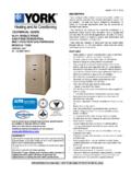
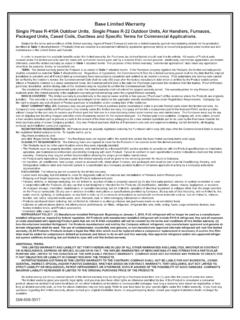
1 TECHNICAL GUIDELX SERIESSPLIT SYSTEM AIR CONDITIONERS13 SEER R-410A 3 THRU 5 NOMINAL TONSMODELS: TCD30 THRU 60 Due to continuous product improvement, specifications are subject to change without us on the web at and rating information can be found at SUMMARY*Standard 1-Year limited parts 5-Years limited compressor warranty.*Does not apply to R-22 models or internet Limited Warranty certificate in User's Information Manual for INSTALLATION IN ALL US REGIONS AND CANADAI nstallation Allowed 5271027-YTG-A-0916 FOR DISTRIBUTION USE ONLY - NOT TO BE USED AT POINT OF RETAIL SALEDESCRIPTIONThe TCD models are the latest iteration in our successful LXSeries split system air conditioner lineup. Optimized for the 3phase 13 SEER National Minimum Efficiency, these outdoorunits are specifically designed to be matched with York indoorcoils, furnaces, and air handlers to provide a complete Small Footprint - Minimum footprint for easier handling,transportation, and installation.
2 Easier Installation - Independent panels provide quickaccess for unit setup. Installation time is reduced by easypower and control wiring access. Options are provided forindoor piston or TXV. The factory installed filter-drier and fac-tory charge for a 15-Ft lineset means less time spent brazingand charging the system. The small base dimension andreduced unit clearances make for easier retrofits. Accessible Information - QR code on unit provides quickaccess to technical documents and warranty information. Durable Finish - The coated steel wire fan guard, coatedexternal fasteners, and pre-treated G90-equivalent galva-nized steel chassis components resist corrosion and rustcreep. Champagne colored powdercoat paint further protectsexternal panels. Quality Coils - The high efficiency microchannel aluminumcoil is manufactured using an improved material system pro-viding reliable performance and small unit size. Rugged Coil Protection - Coils are protected from mechan-ical damage by a proven stamped steel coil guard design.
3 Protected Compressor - Compressors are protected inter-nally by a high pressure relief valve and a temperature sen-sor, and externally by the system high pressure switch. Theliquid line filter-drier is factory installed to protect the com-pressor against moisture and debris. Reliable Operation - Ball bearing fan motors provide supe-rior performance in extreme temperatures. Environmentally Friendly - CFC-free R-410A refrigerantdelivers environmentally friendly performance with zeroozone depletion. Top Discharge - Warm air is blown up, away from the struc-ture and any landscaping and allows compact location onmulti-unit applications. Low Operating Sound Levels - Developed using CFD andFEA tools, the sturdy cabinet and top design provides soundperformance of 77 dBA or lower. Compatible accessories forfurther sound reduction are also available. Better Service Access - Diagonal base valves with openaccess for low-loss fittings, single panel access to the electri-cal controls, swing out control box for full corner access, andremovable fan guard allow easy access for unit mainte-nance.
4 Agency Listed - Safety certified by CSA to UL 1995 / Performance certified to ANSI/AHRI Standard 210/240in accordance with the Unitary Small Equipment Controls Unitary ProductsLIST OF SECTIONSDESCRIPTION .. 1 FEATURES .. 1 NOMENCLATURE .. 2 PHYSICAL AND ELECTRICAL DATA .. 3 DIMENSIONS .. 3 SYSTEM CHARGE FOR VARIOUS MATCHED SYSTEMS .. 4 COOLING CAPACITY - With Air Handler Coils .. 5 COOLING CAPACITY - Upflow, Downflow & Horizontal Furnaces and Coils (Coil Only Ratings) .. 12 COOLING CAPACITY - With High Efficiency Motor Furnaces .. 14 APPLICATIONS AND ACCESSORIES .. 66 SOUND POWER RATINGS .. 66 MECHANICAL SPECIFICATIONS .. 67 TYPICAL INSTALLATION .. 68 TYPICAL FIELD WIRING .. 69 ALTERNATIVE INSTALLATION CLEARANCES .. 69 PERFORMANCE DATA - TON 230 Volt .. 70 PERFORMANCE DATA - TON 460 Volt .. 74 PERFORMANCE DATA - 3 TON 230 Volt .. 78 PERFORMANCE DATA - 3 TON 460 Volt .. 82 PERFORMANCE DATA - 3 TON 575 Volt .. 86 PERFORMANCE DATA - TON 230 Volt.
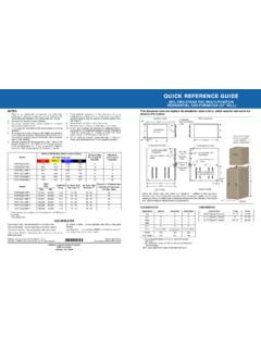
5 90 PERFORMANCE DATA - TON 460 Volt .. 94 PERFORMANCE DATA - 4 TON 230 Volt .. 98 PERFORMANCE DATA - 4 TON 460 Volt .. 102 PERFORMANCE DATA - 4 TON 575 Volt .. 106 PERFORMANCE DATA - 5 TON 230 Volt .. 110 PERFORMANCE DATA - 5 TON 460 Volt .. 112 PERFORMANCE DATA - 5 TON 575 Volt .. 114 NOMENCLATUREBRANDTT = Factory BrandedPRODUCT TYPECC = Air ConditionerNOMINALSERIES EFFICIENCYAND STAGINGDD = 13 SEER / 1-Stage (US Northern Region)NOMINALUNIT CAPACITY(MBH)3630 = Ton48 = 4 Ton36 = 3 Ton60 = 5 Ton42 = TonREFRIGERANTBB = R-410 AVOLTAGE(Voltage-Phase-Hertz)33 = 208/230-3-604 = 460-3-605 = 575-3-60 GENERATION(MAJOR REVISION)11 = 1st Gen2 = 2nd GenetcFACTORY OPTIONSS = Standard (No Options)STYLE LETTER(MINOR REVISION)NOT USED FOR ORDERINGAA = Style AB = Style Betc5271027-YTG-A-0916 Johnson Controls Unitary Products3 Adapter fitting must be field installed for the required 1-1/8 line dimensions are in inches and are subject to change without height is from bottom of base pan to top of fan length and width include screw AND ELECTRICAL DATAMODELTCD30B31 STCD36B31 STCD42B31 STCD48B31 STCD60B31 STCD30B41 STCD36B41 STCD42B41 STCD48B41 STCD60B41 STCD36B51 STCD48B51 STCD60B51 SUnit Supply Voltage208-230V, 3 , 60Hz460V, 3 , 60Hz575V, 3 , 60 HzNormal Voltage Range 11.
6 Rated in accordance with AHRI Standard 110-2012, utilization range A .187 to 252432 to 504540 to 630 Minimum Circuit Overcurrent Device Amps 22. Dual element fuses or HACR circuit breaker. Maximum allowable overcurrent Overcurrent Device Amps 33. Dual element fuses or HACR circuit breaker. Minimum recommended overcurrent HeaterNoNoNoNoNoNoNoNoNoNoNoNoNoFactory External Discharge MufflerNoNoYesNoNoNoNoYesNoNoNoNoNoFan Diameter Inches22222424262222242426222426 Fan MotorRated HP1/81/41/41/41/41/81/41/41/41/41/41/41/ 4 Rated Load Amps RPM1075850850850850107585085085085085085 0850 Nominal CFM2950327535003500430028503200365036504 075330035504125 CoilFace Area Sq. Ft. Deep1111111111111 Fins / Inch23232323232323232323232323 Liquid Line Set OD (Field Installed)3/83/83/83/83/83/83/83/83/83/8 3/83/83/8 Vapor Line Set OD (Field Installed)44. For applications with non-standard vapor line sizes, see the Applications & Accessories section of this Technical 3/43/47/87/81-1/8 3/47/81-1/8 Unit Charge (Lbs.)
7 - Oz.) 55. The Unit Charge is correct for the outdoor unit, smallest matched indoor unit, and 15 feet of refrigerant tubing. For tubing lengths other than 15 feet, add or subtract the amount of refrigerant, using the difference in actual lineset length (not the equivalent length) multiplied by the per foot - 34 - 145 - 24 - 155 - 124 - 34 - 145 - 24 - 155 - 124 - 144 - 155 - 12 Charge Per Foot, Weight $ $DIMENSIONSUnitModelDimensions(Inches)Re frigerant ConnectionService Valve SizeABCL iquidVaporTCD30B(3,4)1S3029-1/4 29-1/4 3/8 3/4 TCD36B(3,4,5)1S36-1/4 29-1/4 29-1/4 TCD42B(3,4)1S33-1/4 35-1/4 31-3/47/8 TCD48B(3,4,5)1S33-1/4 35-1/4 31-3/4 TCD60B(3,4,5)1S36-1/43834-1/47/8 5271027-YTG-A-09164 Johnson Controls Unitary ProductsCHARGING PROCEDURES:1. Check the Factory Unit Charge listed on the unit nameplate to verify the refrigerant charge for the outdoor unit, the smallest matched indoor unit, and the 15 feet ofinterconnecting Verify the indoor metering device and additional charge required for the specific matched indoor unit in the system using the above Add additional charge for the amount of interconnecting lineset tubing greater than 15 feet at the rate specified in Physical and Electrical Data For installations requiring additional charge, weigh in refrigerant for the specific matching indoor unit and actual lineset Once the charge adders for matched indoor unit and for lineset have been weighed in, verify the system operation against the temperatures and pressures in the Charging Chart for the outdoor unit.
8 Locate Charging Charts on the outdoor unit and also in the Service Data Application Guide on Follow the Subcool or Superheat charging procedure in the Installation Manual according to the type of indoor metering device in the system, and allow ten minutes after each charge adjustment for the system operation to stabilize. Record the charge adjustment made to match the Charging Permanently stamp the unit nameplate with the TOTAL SYSTEM CHARGE defined as follows: TOTAL SYSTEM CHARGE = Base Charge (as shipped) + charge adder for matched indoor unit + charge adder for actual lineset length + charge adjustments to match the Charging CHARGE FOR VARIOUS MATCHED SYSTEMS Outdoor Unit TCD30B(3,4)1 STCD36B(3,4,5)1 STCD42B(3,4)1 STCD48B(3,4,5)1 STCD60B(3,4,5)1 SRequired TXV 1,21. For applications requiring a TXV, use S1-1 TVM** series A TXV kit must be used with these indoor units to obtain system Unit 3,4,53. Systems matched with furnaces or air handlers not equipped with blower-off delays may require blower Time Delay Kit CF coils cannot be used in horizontal Charge adders shown above do not indicate that coils are rated for every application.
9 Refer to Performance Data Tables for actual performance for specified sys-tem matches. Obtain certified system ratings from Charge, ozAP18B AP24B AP30B2 AP36B20 AP36C22 AP42C220 AP48(C,D) 520 AP60(C,D) 920AE18B AE24B AE30B0 AE36(B,C)20 AE42C 52 AE48(C,D) 520 AE60C 920AE60D 292220 AVC18B AVC24B AVC30B0 AVC36(B,C)20 AVC42C 52 AVC48(C,D) 520 AVC60C 920 AVC60D 292220CF/CM/CU18(A,B) CF/CM/CU24(A,B) CF/CM/CU30(A,B,C)0 CF/CM/CU36(A,B,C,D)20 CF/CM/CU42(B,C,D)220 CF/CM/CU48(C,D) 520 CF/CM/CU60(C,D) 920CF/CM64D 292220 Some of the combinations shown in the above System Charge table require Advanced Main Air Circulating Fan indoor product. For approved coilonly matches, please see the COOLING CAPACITY - Upflow, Downflow & Horizontal Furnaces and Coils :5271027-YTG-A-0916 Johnson Controls Unitary Products5 COOLING CAPACITY - With Air Handler Coils UNITMODELAIR HANDLERCOILMODEL1 COOLINGMODELWIDTHRATEDCFMNET on next Controls Unitary on next CAPACITY - With Air Handler Coils (Continued)UNITMODELAIR HANDLERCOILMODEL1 COOLINGMODELWIDTHRATEDCFMNET Controls Unitary on next CAPACITY - With Air Handler Coils (Continued)UNITMODELAIR HANDLERCOILMODEL1 COOLINGMODELWIDTHRATEDCFMNET Controls Unitary on next CAPACITY - With Air Handler Coils (Continued)UNITMODELAIR HANDLERCOILMODEL1 COOLINGMODELWIDTHRATEDCFMNET Controls Unitary on next CAPACITY - With Air Handler Coils (Continued)
10 UNITMODELAIR HANDLERCOILMODEL1 COOLINGMODELWIDTHRATEDCFMNET Controls Unitary on next CAPACITY - With Air Handler Coils (Continued)UNITMODELAIR HANDLERCOILMODEL1 COOLINGMODELWIDTHRATEDCFMNET Controls Unitary Products11 = Not Modular Air Handlers use Coil Only in accordance with DOE test procedures (Federal Register 12-27-79 and 3-18-88) and ANSI/AHRI Standard 210/240. Cooling MBH based on 80 F entering air temperature, 50% RH (Relative Humidity), and rated air (Energy Efficiency Ratio) is the total cooling output in BTUs at 95 F outdoor ambient divided by the total electric power in watt-hours at those (Seasonal Energy Efficiency Ratio) is the total cooling output in BTUs during a normal annual usage period for cooling divided by the total electric power input in watt-hours during the same CM coils available with a factory installed horizontal drain pan. See price pages for specific model CAPACITY - With Air Handler Coils (Continued)UNITMODELAIR HANDLERCOILMODEL1 COOLINGMODELWIDTHRATEDCFMNET Controls Unitary ProductsCOOLING CAPACITY - Upflow, Downflow & Horizontal Furnaces and Coils (Coil Only Ratings) UNIT MODELCOILCFM RANGE( )