Transcription of Design & Simulation of Electro-Pneumatic System Using PLC ...
1 Ministry of Higher Education & Scientific Research University of Technology Control & Systems Engineering Department Mechatronics Branch Design & Simulation of Electro-Pneumatic System Using PLC Automation Studio "Supervised by" Dr. Majid Ahmed "By" Aya Moowafaq Abd Elsatar 2009-2010 I ) ( II III IV This project presents a study of the Electro-Pneumatic Control System and its Design Using PLC, As well as an introduction to it's used in applications with mentioned few of those applications, also types of circuits that use this kind of control System and we will have one type of these circuits which will be discussed in details in chapter Three and the Design of an electro -pneuamtic System with PLC with its Simulation while at chapter four there will be conclusion of what we've understand when Using such type of control System .
2 V Subject Page Chapter One 1 3 1 Introduction 1 electro pneumatic systems 1 Advantage of electro pneumatic System 2 Disadvantage of electro pneumatic System 3 Chapter Two 4 13 Introduction 4 Applications 4 Sequential Circuit 6 Cascade Circuit 9 Cycle Diagram 13 Chapter-Three 14-36 Introduction 14 Sequential Switching Method 16 The Application Being Used 17 The Design of The Electro-Pneumatic Application 17 The Connecting of The pneumatic Circuit 18 The Connecting of PLC Electric Circuit 20 Simulation 23 Chapter Four 37 Conclusion & Suggestion for the Future 37 References 38-39 Appendix 40-42 Table of Contents CHAPTER ONE INTRODUCTION CHAPTER TWO electro pneumatic CONTROL System CHAPTER THREE Design & Simulation FOR electro -PNUEMATIC System WITH PLC CHAPTER FOUR CONCLUSION & SUGGESTION FOR THE FUTURE References Appendix 1 CHAPTER-ONE INTRODUCTION 1.
3 INTRODUCTION:- The automation systems that use Electro-Pneumatic technology are formed by mainly three kinds of elements: actuators or motors, sensors or buttons and control elements like valves. Most of the control elements used to execute the logic of the System were substituted by the PLC (Programmable Logic Controller) [1], (a program stored in the central unit of a computer determines the execution of operations in function of the state of the controlled variables. The commands written by an electronic programmer or by a microcomputer) [2]. Sensors and switches are plugged as inputs and the direct control valves for the actuators are plugged as outputs. An internal program executes all the logic necessary to the sequence of the movements, simulates other components like counter, timer and control the status of the System [1].
4 With the use of the PLC, the project wins agility, because it is possible to create and simulate the System as many times as needed. Therefore time can be saved, risk of mistakes reduced and complexity can be increased Using the same elements [1]. A conventional PLC, that is possible to find on the market from many companies, offers many resources to control nor only pneumatic systems, but all kinds of System that uses electrical components. The PLC can be very versatile and robust to be applied in many kinds of application in the industry or even security System and automation of buildings [1]. electro pneumatic Systems:- The most used pneumatic actuation systems are electrically controlled systems. These systems are called Electro-Pneumatic actuation systems [2]. Electro-Pneumatic control System is a combination of electrical unit and pneumatic control unit both in one unit.
5 A number of Electro-Pneumatic elements are used in Introduction Chapter one 2electro- pneumatic controls. In Electro-Pneumatic circuits solenoid operated directional control valves, limit switches and pressure switches are used [4]. On an automation System one can find three families of components, which are sensors, valves and actuators [1]. A solenoid is used in pneumatic valves to act as the actuating element. An adequate technique is needed to project the logic circuit to integrate all the necessary components and execute the sequence of movements properly. For a simple direct sequence of movement an intuitive method can be used [1], but for indirect or more complex sequence the intuition can generate a very complicated circuit and signal mistakes.
6 It is necessary than to use another method that can save time of the project, make a clean circuit, can eliminate occasional signal overlapping and redundant circuits. The present method is called step-by-step or algorithmic [3], it is valid for pneumatic and Electro-Pneumatic , the method consists of designing the systems based on standard circuits made for each change on the state of the actuators, and these changes are called steps. The first part is to Design those kinds of standard circuits for each step, the next task is to link the standard circuits and the last part is to connect the control elements that receive signals from sensors, switches and the previous movements, and give the air or electricity to the supply lines of each step [1]. Advantages of Electro-Pneumatic Systems:- A number of arguments recommend the use of such systems: The System allows easy automation of complex industrial processes.
7 The high speed of signal transmitting and processing leads to the significant enhancement of the productivity of the automation System . Electric equipment costs less than pneumatic equipment. Significant loads are controlled with a reduced control signal. The loading gauge of the control equipment is reduced. Electronic programmers and process computers are used for the control of the System [2]. Introduction Chapter one 3-ystems:Sneumatic P-Disadvantages of The systems use two supply units ( pneumatic and electric). Functioning is not allowed in flammable environments, in environments subjected to hazard of explosion or in high humidity conditions. Hazard of electrocution is present [2]. 4 CHAPTER TWO Electro-Pneumatic Control System electro -pneumatics is successfully used in many areas of industrial automation.
8 Production, assembly and packaging systems worldwide are driven by Electro-Pneumatic control systems [16]. The change in requirements together with technical advances has had a considerable impact on the appearance of controls. In the signal control section, Electro-Pneumatic controllers have the following advantages over pneumatic control systems: 1. Higher reliability (fewer moving parts subject to wear) 2. Lower planning and commissioning effort, particularly for complex controls 3. Lower installation effort, particularly when modern components such as valve terminals are used 4. Simpler exchange of information between several controllers. Electro-Pneumatic also used for remotely controlled System where a few sensors are added to assure the safe operation [17]. -Applications: There are so many industry application of electro pneumatic System , these applications can be divided into:- 1.
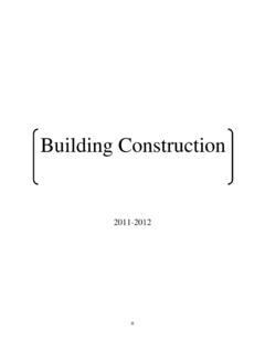
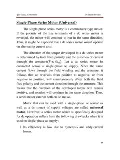
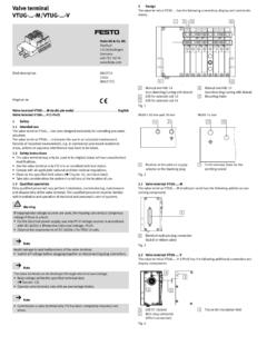
9 Temperature control [5]. 2. Transportation (cement powder, grain and other materials) [6]. 3. Packaging [7]. 4. Filling as in figure (1) Chapter Two Electro-Pneumatic Control System 5. Level gauging [8]. 6. Printing as in figure (2). Figure (1): Electro-Pneumatic filling Machine for liquids, creams, semi-solids [14]. Chapter Two Electro-Pneumatic Control System Figure (2): Electro-Pneumatic Printing Machine [9]. -:ircuitCequential S 32. By sequencing a number of pneumatic cylinders, various machining and tooling operations may easily be obtained in a machine. By Using this technique, the cylinders can be actuated one after another in sequences like clamping, feeding and ejecting (or) lifting, pushing and clamping (or) in various other combinations.
10 The Electro-Pneumatic circuit utilizing this technique is known as automatic sequencing circuit. Correct sequence of motion of each cylinder and the respective cycle time, should be carefully studied before designing such a circuit. So, Process control electro -pneumatics is also called as sequencing. It means performing number of actions one after another which follows each other in a simple order or with an order determined by sensors [10]. Chapter Two Electro-Pneumatic Control System Case Study 1 The circuit below is a closed loop circuit. When the solenoid is activated, current is supplied to valve A+, cylinder A extends (on) to the a+ position and current is obtained from the sensor at the a+ position and supplied to valve B+ and so on.