Transcription of Proportional and Servo Valve Technology - Moog Inc.
1 Proportional and Servo Valve Technology8 Fluid Power JournalMarch/April 2003 The ability to achieve automated stepless control ofpressure and flow rate in fluid power systems hasundergone major development in the past twenty-fiveyears. Electrohydraulic Servo valves were invented in the late1930s as a high tech, though high cost, solution to motioncontrol needs. The mid-1980s saw the practical introductionof Proportional valves as a viable and reasonably pricedalternative to Servo valves . This article will explore thetechnology used in these Proportional and Servo valves aswell as attempting to shed some light as to what type ofvalve may be most appropriate for a given true, stepless control of pressure or flow wasn t thatcritical to the operation of a machine, preset pressure orflow control valves could be achieved by having a bank ofpreset valves . The appropriate Valve would be connectedinto the circuit via the actuation of a solenoid Valve .
2 Forexample, three discrete pressures could be achieved byhaving two pilot relief valves connected in parallel to thevent port of a ventable pilot operated relief Valve . Thesetwo valves would be isolated from the pilot operated reliefvalve by two-way normally-closed solenoid valves . By indi-vidually actuating the 2-way valves , three different pressurescould be achieved. But what if stepless pressure control wasrequired? What if the pressure increase or decrease neededto follow a specific rate? What if that rate change wasn tconstant? Then what could the machine designer do? Until the invention of Servo valves , if the need existed toachieve varying pressure to an actuator in an effort tocontrol force or torque, one needed to either have themachine operator turn an adjustment knob, stroke a lever,or a mechanical means needed to be designed to have amechanical input device or linkage vary the setting of thevalve.
3 The same need held true if flow needed to be control of a Valve could be fairly control of the Valve , while possibly being moreconsistent and repeatable, might not offer much flexibilityfor different adjustment electrical machine control systems were not all thatwell developed until the introduction of the micro-processor in the early 1980s. As most machines that hadelectrical automation used relay logic, the sequence ofoperations of the machine was not easily revised. Relays aredigital, or on-off, devices. The introduction of themicroprocessor, and hence, the PLC (programmable logiccontroller) opened the door to a great amount of controloptions to machine designers. The operation sequence of amachine was no longer hardwired in relay logic. WhileBoolean operations were possible in relay logic, it wasinconvenient to do so, as well as difficult, expensive, andtime consuming to accomplish.
4 The common introductionof PLCs and Proportional valves greatly expanded thecontrol options available to machine initial Proportional valves that appeared on themarket are what are now commonly termed open-loop valves . In contrast to mechanical feedback (MFB) servovalves, a feedback link does not exist between the coilassembly and the Valve spool. Since a feedback loopbetween the input command and the Valve output doesnot exist, the feedback loop is op en rather than closed. Inan effort to improve the performance of proportionalvalves, relative to the performance of Servo valves ,manufacturers added linear variable displacementtransducers (LVDTs) to Proportional valves in order to sensethe spool (or poppet) position. The output signal from theLV DT w a s f e d b a c k to the amplifier card. A summingamplifier on the amplifier card calculated the differencebetween where the spool was supposed to be and where itactually was, and the output to the coil was changed in aneffort to position the spool to achieve the desired outputbased on the input.
5 These enhanced Proportional valves aretermed closed loop Proportional valves . Since the meansof feedback is electrical, not mechanical, this gave rise to theterm electrical feedback (EFB).How Proportional valves Operate:An electrical input from some source is wired to anamplifier card, which in turn, controls a coil on theproportional Valve . Since the electrical input from mostsources is generally much lower in power than the amountof current required to operate the coil, the input currentmust be amplified. This function is fulfilled by an amplifiercard. The amplifier may be mounted on the Valve , some-times termed OBE (on board electronics) or be remotefrom the Valve . The source of the input may come from several devices, including a potentiometercontrolled by the machine operator, frompreset potentiometers, a joystick, or from amplifier card drives the Valve coil witha current signal.
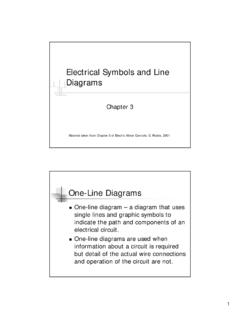
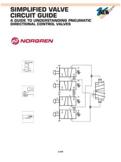
6 As the current flowsthrough the coil, electromotive force isdeveloped, causing the armature of thesolenoid assembly to move. The armature, inturn, inputs force to the Valve spool, in a flowcontrol, pressure reducing , or directionalcontrol Valve , or the poppet in a pressurerelief Valve . The spool or poppet is offset by aspring. Therefore, the force input by thesolenoid assembly is opposed by the force ofthe Proportional directional controlvalves, such as the Valve illustrated in Figure1, have two solenoid assemblies, onesolenoid being located at each end of thevalve. Proportional directional control valvesprovide control of direction as well as offlow. This particular Valve includes an the most part, dual coil proportionalvalves are based on standard on-offdirectional valves . The major differencesbetween direct acting on-off (sometimestermed bang-bang) and direct actingproportional directional valves are:1) The centering springs in proportionaldirectional valves are stronger than thecentering springs used in on-off ) Proportional solenoids are engineered toproduce more force than do on-off ) Proportional valves always use DC ) While the bodies of on-off valves andproportional valves are almost always identical(the same body part is used for both versionsby most manufacturers), the spools inproportional valves :a) are tailored to the flow rate the Valve isdesigned to control;b) are available in a range of flow rateswithin a Valve size;c) and have metering notches that providefor a variety of flow rate profiles vs.
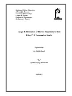
7 Theelectrical command input to the ) Spools for directional controls areavailable 1:1 and 2:1 flow ratios between thetwo work ports to allow for control ofhydraulic motors and double rod cylindersand 2:1 area ratio Proportional directional valves haveonly one coil. These valves typically havefour, rather than three, position 2 shows a schematic for a 4/4 (4-way,4-position) single coil Proportional that in the de-energized condition(extreme left flow envelope), all ports areclosed. In order to shift the spool to the c e n t e r p o s i t i o n , t he spool must travelthrough a condition in which flow from thepressure port will connect to one of theworking ports, as the opposite working portis connected to tank. Though the spoolpasses through this active flow conditionvery rapidly, its affect on the system stillmust be considered. As the solenoid assemblyis completely de-energized, either as part ofthe machine control sequence or in the caseof an electrical failure, the possibility ofunwanted actuator movement must beconsidered.
8 solenoid operated blockingvalves located in the working lines betweenthe Proportional Valve and the actuator maybe used to prevent unwanted actuatormovement. These single coil 4-waydirectional valves tend to be high performancevalves, relative to dual coil proportionalvalves. These valves are termed, by somemanufacturers, as ser vo-propor tional valves , indicating their higher dynamicperformance. This higher performancecapability stems from the fact that thedisplacement of the spool from the centerposition of the Valve is not influenced bythe hysteresis typical of the centering springsfound in a dual coil Proportional , how does a Proportional coil actuallywork? All coils used on Proportional valvesare direct current (DC) coils. AC coils have aninrush current approximately five timesgreater than their holding current. If thearmature in an AC solenoid assembly is notallowed to completely shift into position, itscurrent draw will remain high.
9 The coil willoverheat and burn out; an AC is notdesigned to handle a sustained amp drawfive times its holding amp draw. DCsolenoids don t exhibit inrush current, so thearmature can remain partially shifted indefinitelywithout an increase in amp draw. By virtue ofbeing able to partially shift the armature, thespool or poppet may be partially shifted aswell, resulting in a partial output from simplest means of varying the currentused to drive a Proportional coil would be tolocate a rheostat (adjustable resistor)between a DC power supply and the problem with this solution is that anycurrent that isn t directed to the coil will bechanged into heat. This is analogous to usinga fixed displacement pump at less than itsrated flow to supply an actuator. Just as theexcess pump flow is directed to tank over arelief Valve at full pressure drop, generatingheat, excess amperage will dump over thethird leg of the rheostat, generating heat asthe power supply delivers full amperage atfull current to the rheostat.
10 A more efficientmeans of controlling the Proportional coil much more effective method of partiallyshifting an armature is to send a pulse widthmodulated (PWM) current signal to the is a technique in which an on/offtransistor located on the amplifier card turnscurrent to the coil on and off very the switching transistor turns off theunneeded current, unneeded current doesnot need to be dissipated, thereby reducingheat generation. Low frequency PWM is inthe range of 100 to 400 hertz (Hz, cycles persecond) while high frequency PWM is in therange of 4000 to 5000 Hz. As the pulse rateremains constant, the duration of the pulse isvaried. For example, if the width of the pulseis 30% of its maximum duration, theoreticallythe Valve should shift enough to deliver a30% output of flow or pressure, whichever isbeing controlled . By the same token, if thewidth of the pulse is 80% of its maximumduration, the Valve output should be at 80%.