Transcription of DESIGN AND MODELLING OF BLDC MOTOR FOR …
1 42 Int. J. Elec& 2015E Elakkia et al., 2015 DESIGN AND MODELLING OF BLDC MOTOR FORAUTOMOTIVE APPLICATIONSE Elakkia1*, S Anita1, R Girish Ganesan1 and S Saikiran2*Corresponding Author:E Elakkia, paper presents DESIGN , simulation and analysis of three phase BLDC MOTOR for automotiveapplications. Finite Element Analysis (FEA) of the BLDC MOTOR is done to confirm the flux linkagecharacteristics of the DESIGN . The proposed BLDC MOTOR is designed and simulated using FEAbased DESIGN software tool MotorSolve. Simulation results from the DESIGN software tool focuseson the torque and magnetic flux density distribution.
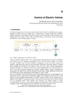
2 The BLDC MOTOR is modelled using MATLAB/SIMULINK and the dynamic characteristics of PMBLDC MOTOR are :Finite Element Analysis (FEA), BLDC MOTOR , Electronic commutationINTRODUCTIONThe BLDC MOTOR is the most preferredmachine for automotive application, as it hashigh reliability and efficiency. It has thecapability to provide large volume of torquefor wide speed ranges. Electroniccommutation technique and permanentmagnet rotor cause BLDC to have immediateadvantages over brushed DC MOTOR andinduction MOTOR in electric vehicle application[6], [15], [17].
3 The BLDC MOTOR construction is similar tothe ac permanent magnet synchronous motorwith permanent magnets on the rotor andwindings on the stator [12]. The energizedISSN 2319 2518 Issue, Vol. 1, No. 1, March 2015 National Level Technical Conference P&E- BiDD-2015 2015 IJEETC. All Rights ReservedInt. J. Elec& 20151 RMK Engineering College, Electrical Drives India Pvt. Ltd., Bangalore, windings create electromagnet polesand permanent magnets create the rotor rotating field is created on the stator andmaintained, by using the appropriatesequence to supply the stator phases.
4 Theenergized stator phase attracts the rotor. Thisaction of rotor chasing after the electromagnetpoles on the stator is the fundamental actionused in brushless permanent magnet BLDC MOTOR operates based on the rotorposition information. According to the rotorposition, the phase windings are switched ina sequence to obtain the rotation [14] [16]. Thetorque developed in BLDCM is affected by thewaveform of back-Emf. Usually the BLDC MOTOR has trapezoidal back-Emf waveformResearch Paper43 Int. J. Elec& 2015E Elakkia et al.
5 , 2015and stator is fed by rectangular stator currentand theoretically it gives a constant torque butthe torque ripple exists due to current ripple,emf waveform imperfection and phase currentcommutation [13].Electronic commutation of BLDC Motorcontrol algorithm is more complex comparedto other MOTOR types. Therefore accurate modelof MOTOR is required to have complete andprecise control scheme of BLDC. A motormodel providing torque for related values ofcurrent and back emf is required to DESIGN thedrive system [15].
6 On obtaining the analytical designparameters the electromagnetic analysis isgenerally done using finite element methodwhich provides solutions based on numericalmethods. The method basically involves thediscretization of the MOTOR cross-section intosmaller areas called finite elements. By usingFEM, it is possible to make the accurate fieldcalculations in the electrical machines [7].ANALYTICAL DESIGNThe analytical designing available in MotorSolve provides an initial DESIGN of a motormodel. It gives a complete DESIGN includingdimensions, winding layout, phase coil detailsand end turn electrical order to determine the size of a radial fluxmotor that will produce a required torque, thefollowing scaling law can be used [9].
7 2 (1)rTKD L wherek is a constant,Dr is the rotor outerdiameter andL is the stack , (2 )sLr D (3)rsDDf whereDs is the stator outer diameter,ris motoraspect ratio andfis rotor-stator ratio, (1) canbe expressed as:3 ( 4)rrTKDf Approximate expressions for stator androtor dimensions can be obtained relating thedimensions of the ferromagnetic portions ofthe MOTOR to the number of magnet poles, thenumber of slots and the rotor outside radiusTooth width, (5 )rgtbssttD BwN K B Back iron Depth, (6)2rgsymsttD BwN K B Core thickness, (7)2rgrymst ryD BwN K B where,Ns is No.
8 Of slots,Nm is No. of poles,Kst is Stacking ,Bsy,Bry are fixedmaximum flux density specified in the statorteeth, the back iron depth and rotor core andBg, Flux density in the air balance between the input powerPi,the mechanical powerPm and the windingslossesPl is expressed as: ( 8)imlPPP Input power is given by,cos ( 9)iph rms rmsPN VI where,1 ( 1 0 )223peaklin er m sVVV the mechanical power is given by2 (11)60mr pmPTV T 44 Int. J. Elec& 2015E Elakkia et al.
9 , 2015and the losses (include the Ohmic loss in thecoil sides only, the losses in the end turns aswell as the core losses are not taken intoaccount) are given by2 ( 12)lssrm sPN R I where, (13)slLRN NA where,Nph is No. of phases,Ns is No. of slots,Irms is Rated current,Vline is supply voltage, is coil material conductivity,Nl is No. of layers,N is turns andAw is conductor area [4]and [8].FINITE ELEMENT ANALYSISOF BLDC MOTOR USINGMOTORSOLVET hree phase, four pole BLDC is designedusing FEA based DESIGN software MotorSolveBLDC.
10 Results obtained are Of BLDC MOTOR UsingMotorsolve BLDC SoftwareMotorSolve BLDC is electric MOTOR designsoftware for brushless dc and permanentmagnet AC machines which provides easy-to-use templates and an automated-FEAsolver to calculate performance. Meeting thegrowing demand for higher efficiency andlower costs requires software that deliversreliable results and does not give falsepredictions for crucial performance factorsresulting in avoidable and costlycomplications. Modern electric motorsperformance cannot be predicted by generalapproximations and magnetic circuitcalculations.