Transcription of Design and Verification of VHDL Code for FPGA …
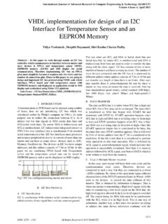
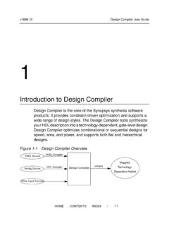
1 IOSR Journal of VLSI and Signal Processing (IOSR-JVSP) Volume 4, Issue 5, Ver. I (Sep-Oct. 2014), PP 12-17 e-ISSN: 2319 4200, p-ISSN No. : 2319 4197 12 | Page Design and Verification of vhdl Code for FPGA Based Slave VME Interface Logic Manju Mohan, Nishi G Nampoothiri (Dept. of ECE, Musaliar College of Engineering. & Technology, Pathanamthitta, Kerala, India) Abstract: Versa Module Europa (VME) bus is used in various applications in order to ensure safety and security. VME64x based Real Time Computer (RTC) system with various types of Input / Output (I/O) hardware modules is being designed and developed for use in various safety critical and safety related Instrumentation & Control (I&C) systems. Analog Output Card (AOC) is one of the I/O hardware modules as part of VME64x RTC development.
2 The AOC uses Field-Programmable Gate Array (FPGA) as VME bus system controller. This paper discusses the Design and development of a VME64x bus controller so as to meet the required specifications correctly. Keywords: A16/A24/D16 Bus interface, Analog Output Card (AOC), Field Programmable Gate Array (FPGA), VHSIC Hardware Description Language ( vhdl ), VME64x bus I. Introduction VME64x is a Mechanical and Electrical superset of original IEEE 1014-1987 and VME64 ANSI/VITA 1-1994 standard. This VME bus system consists of a processor card, Analog I/O cards and Digital I/O cards. Analog Output Card (AOC) is one of the I/O hardware modules that is used as part of VME64x RTC development. AOC designed for the display and control applications in the Instrumentation & Control systems consists of buffers/transceivers, bus interface logic, Digital to Analog Converters (DAC), isolation and read back control mechanism (Isolation, Multiplexers, amplifiers and Analog to Digital Converter (ADC)).
3 Buffers are used to buffer the VME side signals. Field Programmable Gate Array (FPGA) is used for bus interfacing or the VME bus system controller which implements the complex bus control functions like bus interface, control signal generation for output and read-back paths. This paper discusses the Design of a bus interface and analog output controller for a VME64x based Analog Output Card. The designed VME64x based slave interface logic interfaces the standard VME64x cycles to the required user cycles. The bus interface features includes: Data mode: D16 Address modes: A16 or A24 Read, write cycles Programmable rescinding DTACK D16 interrupt logic. It follows IEEE 1014-1987{VME} FPGA [1] is chosen as it has advantages over an Application Specific Integrated Circuit (ASIC) and CPLDs.
4 The main advantage is the ability to reprogram. Hardware description language (HDL) [2] is used to describe the FPGA functionality. In this Design , the coding is carried out by following the standard coding guidelines in VHSIC hardware description language ( vhdl ) as per the specifications. To ensure its correctness, the program is simulated and tested using test bench. FPGA has been selected for implementing the control logic due to its several advantages compared to CPLD, as listed below: 1. Their size, capability and speed are higher. 2. They are far more flexible. 3. They have multi-level logic. The AOC being designed has a special read back feature in it by which DAC outputs in addition to the field current values can be read back after passing through multiplexers and ADC.
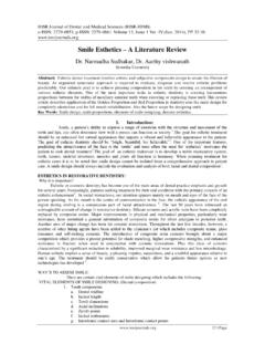
5 As per the requirement, the Register Transfer Level (RTL) code has to be in vhdl . II. An Overview Of VME64x Bus VMEbus [3] is a standardized bus for use in real time computer systems. The bus consists of sub buses that includes data transfer bus, priority interrupt bus, arbitration bus, and utility bus. The data transfer bus is a high speed bus that is used for the data transfers between masters and slaves based on the control signals. The VME bus uses an asynchronous transfer protocol which allows the data transfer to be carried out at high speeds. Design and Verification of vhdl Code for FPGA Based Slave VME Interface Logic 13 | Page Fig. 1: VME Bus System CONTROLLER Controls Access to the Bus Handles Interrupts SLAVE Allows Masters to Read/ Write Access VME MASTER Bus Grant/Request R/W Interrupt Bus Data Bus Address Bus Fig.
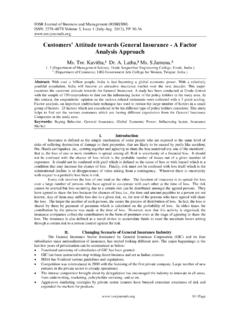
6 2: Write cycle timing diagram Valid Valid Valid Address AM Code AS* Data DS* DTACK* It also has multiprocessing capability. The VME64x bus specification (ANSI/VITA ) is an extension of the VME64 standard ANSIVITA 1-1994. It defines a set of features that can be added to the VME and VME64 boards, backplanes and subracks. The structure of VME bus system is shown in Fig. 1. III. Typical Read/Write Cycle During a typical read/write cycle the master addresses a slave and then transfers Data through the data lines D00-D15 based on the control signals. For read and write operations, data strobes DS0* and DS1* must go low. For a read operation, master initiates the cycle by driving the address bus A01-A15/A01-A23, AM0-AM5, IACK* and LWORD*. These signals should be valid on the falling edge of AS*.
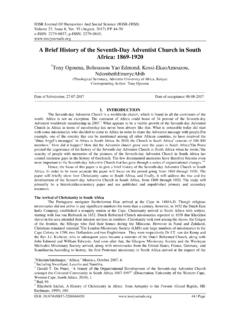
7 WRITE* signal indicates the direction of data transfer. So the master negates WRITE* and asserts data strobes DS0* and DS1*. The slave decodes the address to check for a valid access and if so, the data is placed onto D00-D15 and then asserts data transfer acknowledge [DTACK*]. The master negates the data strobes after latching the data to inform slave the completion of transfer cycle. The slave then negates DTACK* and then the cycle is terminated. A write cycle is shown in the Fig. 2. In case of write cycle, master asserts the WRITE* signal and then places data onto the bus before either data strobe is asserted. IV. Block Diagram of AOC Fig. 3 indicates the top level block diagram of the AOC and it also shows the various interconnections between them.
8 FPGA is chosen as the controller to interface the VME cycles and also to generate the required control signals for the DACs, Multiplexers and ADC. Design and Verification of vhdl Code for FPGA Based Slave VME Interface Logic 14 | Page Fig 3 Block Diagram of VME64x based Analog Output Card VME BUS Isolators MUX (1st level) MUX (2nd level) ADC Read Back Control Mechanism Output Conne-ctor VME64x Interface & Control logic (FPGA) Isolators V/I Convertor (0-3) DACs Parallel DAC (0-2) Parallel/ Serial DAC (3) Amplifier The specifications of the VME64x based analog output card are: 1. Number of channels :4 2. DAC resolution:14 bits 3. span 4. Type of output: Voltage/Current 5.
9 Output range:0-10V/4-20 mA 6. Isolation (Channel-Channel):100 Vrms (continuous) 7. Isolation (Input-Output) :100 Vrms (continuous) 8. Load Resistance :2K (min.) for Voltage output, 600 (max.) for Current output 9. VME bus interface :A16/A24,D16 10. Read-back :Provided for each channel at DAC output Card output(isolated) V. Inputs-Outputs The top level interface of the FPGA is as shown in Fig. 4. These signals are used to control data transfer through the VME interface. The VME side signals are vme_addr (address bus A01-A31), vme_as_n (address strobe AS*), vme_am (address modifier AM0-AM5), vme_ga_n (geographical address GA0*-GA4*), vme_lword_n (long word lword*), vme_iack_n (interrupt acknowledge IACK*), vme_iack_in and iack_out (interrupt acknowledge daisy chain (IACKIN*-IACKOUT*), vme_ds_1_n and vme_ds_0_n (data strobes DS0*-DS1*), vme_write_n (read/write signal WRITE*), irq7_1 (priority interrupt requests IRQ1*-IRQ7*), dtack_n (data transfer acknowledge DTACK*), bidir_data_bus (data bus D00-D31).)
10 Design and Verification of vhdl Code for FPGA Based Slave VME Interface Logic 15 | Page Fig. 4 Signal Interface of FPGA clk reset_n vme_as_n vme_addr vme_am vme_ga_n vme_lword_n vme_iack_n vme_iack_in vme_ds_1_n vme_ds_0_n vme_write_n ADC_busy ADC_data FPGA dtack_n board_sel_sig_n bidir_data_bus iack_out irq7_1 DAC_wr_n DAC_clr_n DAC_data DAC_addr SDAC_sync_n SDAC_sclk SDAC_sdin SDAC_clr_n SDAC_rstin_n ADC_rc_n mux_1_sel mux_2_sel VI. Objectives of FPGA The objectives of FPGA are as follows. 1. Interface with VMEbus. 2. Provide control signals to DAC for Writing/Reading back digital inputs, resetting outputs etc.