Transcription of VHDL implementation for design of an I2C Interface …
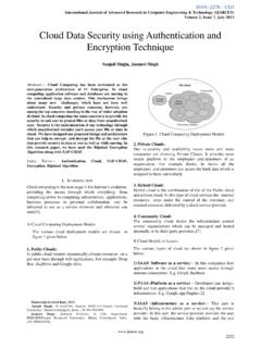
1 International Journal of Advanced Research in Computer Engineering & Technology (IJARCET) Volume 4 Issue 4, April 2015 1571 ISSN: 2278 1323 All Rights Reserved 2015 IJARCET Abstract In this paper we walk through mainly on I2C bus controller which communicates or Interface between master and slave devices ie FPGA and temperature sensor (SE95), EEPROM memory (24C02) and SSD display for serial communication. Therefore implementing I2C bus on FPGA gives more simplicity because it requires only two wires and less number of connections pins. Hence in this paper we are going to design and implement I2C bus protocol using vhdl code which interfaces FPGA board and with temperature sensor with EEPROM memory and displayed on application circuit ie SSD display and synthesized using Xilinx platform.
2 IndexTerms I2 Cbus,Master,Slave, vhdl ,EEPROM(24C0) Temperature Sensor(SE95),Xilinx. I. INTRODUCTION Communication on PCB board can be attained using number of buses, here we are introducing I2C bus which was introduced earlier by Philip s company in 1980,s. Its main purpose was to reduce the connection between IC s. As it utilises two bus line signals ie SDA (serial data line) and SCL(serial clock line). By nature SDA is bidirectional and SCL is unidirectional. I2C (interconnect integrated circuit) or TWI (Two wire Interface ) bus is synchronous 8 bit oriented serial communication bus. I2C bus interfaces main processor and as many peripheral devices ie it consists of more than one master and can have as many slaves devices such as ADC, Memory, Oscillator etc.
3 The devices on I2C bus have unique addresses and this address consists of 7 bit or 10 bit. In this paper we are interfacing FPGA board with Temperature sensor and the temperature sensed data can be stored in EEPROM memory and it can be displayed on SSD display. Fig1: I2C bus configurationuisng master and slaves II. I2C BUS PROTOCAL A. I2C Specification I2C is synchronous 8 bit oriented serial communication bus, which consists of two signal lines and one common ground. The two wires are SCL and SDA ie Serial clock line and Serial data line, by nature SCL is unidirectional and SDA is bidirectional, both lines are used in order to transfer the data along with the clock signal.
4 I2C bus consists of two or more number of masters and have as many as slaves. The number of slave devices connected onto the I2C bus it is addressed by different address where address consists of 7 bit or 10 bit and can transfer any length of data there is no limits. After each data transfer there is acknowledgment bit sent by slave to master or visa versa, to ensure the data is received. And has four standardized speed modes, called standard (100 kbps), fast (400 kbps), fast- plus(1 Mbps) and high-speed( Mbps). B. DATA TRANSFER The data on SDA line it is stable when SCL line is high and when SCL line is low data can be exchanged. The data which is transferred on SDA line begins with START bit and terminates with STOP bit.
5 START operation happens when SCL line is high and SDA line is at falling edge (ie from high to low) and STOP operation happens when SCL line is high and SDA line is at rising edge (ie from low to high). Once this START operation begins bus is considered to be busy, bus becomes free once STOP condition appears. This is followed by 8 bit of device address here the 8th bit is considered to be read/write. If this bit is low than it is considered to perform write operation or else read operation. This is followed by ACK signal ie acknowledgement signal, which indicates that operation is successfully completed. Next byte it is memory address followed by ACK signal, next byte is DATA which is to be written or read from the memory.
6 C. Case of Multiple Master situation In that case, each master will have their own clock and the synchronization issue arises. Therefore, devices are connected in such a way that they are connected as a wired AND conditions. By virtue of the open drain /open collector characteristics of the FETs/Transistors/Gates in Wired AND used as the devices to control the data collision of two masters. This is obtained by Arbitration techniques. That is when one master is transmitting a High level signal, while the other is transmitting a low level signal on the SDA line, the high level signal is allowed & the Low level signal is switched off. The reason being the SDA data must be in synchronous with the SCL while it is in High level.
7 This is one way of arbitration. Another way, is that when two masters are trying to address the same device arbitration continues with the vhdl implementation for design of an I2C Interface for Temperature Sensor and an EEPROM Memory Vidya Venkatesh , Deepthi Dayanand, Shri Kanhu Charan Padhy International Journal of Advanced Research in Computer Engineering & Technology (IJARCET) Volume 4 Issue 4, April 2015 1572 ISSN: 2278 1323 All Rights Reserved 2015 IJARCET comparison of the data- bits to check the whether they are master transmitter or acknowledge bits if they are master-receiver. So the address and data is not lost during this arbitration process as it is determined by the winning master.
8 A master that loses the arbitration can generate clock pulses until the end of the byte in which it loses the arbitration. If a master also incorporates a slave function and it loses arbitration during the address stage, it s possible that the winning master is trying address it. Then the losing master should switch over to slave mode. However, the arbitration is not allowed in repeated start & data, a stop condition & data and a repeated start & stop condition. Also the slave is not allowed in the arbitration procedure. III. PROPSED ARCHITECTURE Figure 2 shown consists of FPGA board which is interfaced with EEPROM memory and temperature sensor and the temperature sensor sense the value and those value will be written into EEPROM memory and it can be displayed on application circuit ie SSD display.
9 This temperature sensor can be used in industry or in ovens etc in order to sense the temperature and indicate the value of the temperature. The interfacing is done using I2C bus protocol which consists two line SCL and SDA these two lines are connected to power supply using pull up resistor and these resistor values depends on number of slave devices connected to master. So if the number of slave device increase the resistor value decreases. Fig 2 : Block diagram of proposed achitecture . Fig 3: Diagram of interfacing IV. IMPLMENTATION OF I2C FOR EEPROM MEMORY (24C02) EEPROM memory it is 256 byte ie 2k bit with 32pages each page consists of 8 byte. A. FEATURES Low-voltage and standard-voltage operation (Vcc = ).
10 InternallyOrganized128x8(1K), 256x8(2K),512x8(4K), 1024x8(8K) or 2048x8(16K). Two-wire serial Interface Write protect pin for hardware data protection. B. PIN CONFIGURTION Fig 4 : Pin configuration of EEPROM memory C. DEVICE ADDRESSING OF EEPROM MEMORY The address of all I2c bus are either 7 bits or 10 bits. But the use of 10 bits are not in general and is not covered here. The modules and all the common chips which we connect to I2c bus will have 7 bit address. This means that I2C bus can have up to 128 devices, since 7 bit number can be from 0 to 127. We always send 8 bit address , the extra bit is used to inform the slave if master is writing to it or reading from it, if bit is zero the master is writing to clave device.