Transcription of DESIGN DRAWING STANDARDS - …
1 DESIGN DRAWING STANDARDS . TM. AND TOLERANCES INDEX. Assembly 05/29/15. PAGE DATE DESCRIPTION. A-1 02/13/08 DESIGN DRAWING STANDARDS and Tolerances Index A-2 09/07/99 Metric Drafting STANDARDS A-3 02/13/08 Metric Drafting STANDARDS A-4 04/06/06 Metric Drafting STANDARDS A-5 05/29/15 Metric Drafting STANDARDS A-6 03/01/96 Tolerance stickers A-7 09/07/99 Installation Torques for Metric Screws A-8 10 02/12/97 Bill Of Materials Instructions A-11 15 02/12/97 System Instructions A-16 18 02/12/97 Assembly Line Instructions A-19 20 09/01/00 Assembly Line Instructions A-21 02/12/97 Tool Instructions A-22
2 09/01/00 Tool Instructions A-23 02/12/97 Tool Instructions A-24 25 09/01/00 Tool Instructions A-26 27 02/12/97 Unit Instructions A-28 29 09/01/00 Unit Instructions A-30 33 02/12/97 Unit Instructions A-34 09/01/00 Unit Instructions A-35 02/12/97 Templates A-36 02/12/97 System Template A-37 09/15/00 Line Template A-38 09/15/00 Tool Template A-39 02/12/97 Unit Template 1997 Auto/Steel Partnership This document is Uncontrolled when printed. A-1. G L O B A L S TA N D A R D C O M P O N E N T S. METRIC DRAFTING. STANDARDS TM.
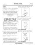
3 Assembly 09/07/99. 1. INTRODUCTION. These Metric Drafting STANDARDS are an integral part of the NAAMS Global A. Standard Components, Assembly. 2. DEFINITIONS. Hard Metric: A dimension in millimeters, established in metric and not a result of converting from customary units to equivalent metric. Soft Metric: A dimension in millimeters, resulting from directly converting an established customary base dimension. 3. DRAWING PROJECTION. Current drafting practices pertaining to multiview and sectional view draw- ings are defined and illustrated in ANSI Y - 1994.
4 All drawings should be drafted using third angle projection on orthographic views. When sections or views are projected on the same or on other sheets, they shall be projected and drawn perpendicular to the cutting or viewing plane. When sections or views are projected onto other sheets, directional arrows shall be shown and cross referencing notes added onto the respective view. 4. CONSTRUCTION MATERIAL. When plate, tubing, angles, channels, etc. that are produced to cus- tomary units are specified, the cross section dimensions should be called out in customary units and the cut length in metric.
5 5. TRANSFERS. Transfers within a tooling system shall have their construction dimensioned in metrics. Travel distance, both horizontal and vertical, shall be dimensioned in metrics, with equivalent customary setup dimensions to interface coordination points with plant facilities and plant equipment. 6. FASTENERS. It is recommended that all tool builders and suppliers use only hard metric fasteners. All metric threads are assumed to be coarse unless otherwise specified. The preferred minimum screw size is M8, except for the attachment of commercial and standard items that have predetermined mounting holes.
6 Fasteners for kits shall remain to their existing standard screw size. 7. ENERGY, INERTIA, TORQUE, POWER AND WORK. These entities shall remain to current STANDARDS . For future customary / metric conversion, refer to the NAAMS Metric Equivalent Charts #1 & #2. 8. DIMENSIONING AND TOLERANCING. Dimensioning and tolerancing practices shall be as defined and illustrated in ANSI Specification # - 1994. A zero before the decimal point shall be used for a number less than (Example ). 1997 Auto/Steel Partnership This document is Uncontrolled when printed.
7 A 2. G L O B A L S TA N D A R D C O M P O N E N T S. METRIC DRAFTING. STANDARDS TM. Assembly 02/13/08. 9. METRIC DRAWING SCALE. For general DESIGN work, DRAWING scales shall be full size wherever possible. The recommended reduced scale for fixture designs are 1:2, 1:5, 1:10, 1:20. and 1:50. When increased scales are necessary, the scales shall be 2:1, 5:1, 10:1. 20:1 and 50:1. The DRAWING scale for system layout drawings should be coordinated with each individual plant. 10. LETTERING. All text height shall be 2 mm minimum on 11 x 17 CAD drawings and 3 mm minimum on all other drawings .
8 Notes and descriptions shall be 5 mm minimum. View callouts, section, unit no's, switch and cylinder callouts shall be 7 mm minimum. 11. BODYLINES. On fixture drawings , only one body line is required in each direction provided its relationship to the zero datum line is shown. These shall be identified with a 25 mm diameter balloon. All auxiliary worklines shall be identified with a 25 mm square box, showing originating bodyline intersection and angle used for worklines. When a dimension originates from a workline, the origin should be indicated.
9 12. DIMENSION ARRANGEMENT. Dimensions should be shown in true views and should not be taken from hidden lines. Dimensions should be located outside the outline of the detail wherever possible. Screw and dowel sizes shall be written along the center-line of the fastener in its side view on assembly drawings . 13. COMMERCIAL COMPONENTS. Metric commercial components are preferred when available and approved by customer. Pivot shaft diameters, bushing & bearing sizes, cylinders and stroke of cylinders etc., shall remain to existing STANDARDS .
10 Gears, racks, etc., shall retain inch pitch diameters. Pipe threads shall remain to existing STANDARDS . 14. SETUP DIMENSIONS. Machined surfaces, pivot centerlines, hole patterns, fab dimensions and NC. block mounting surfaces should be set up in 5 mm increments whenever possible. 15. DETAILS OF A UNIT. All items that are detailed shall be identified with a 20 mm diameter split balloon with the item number of the detail in the top half and the sheet number where the detail is drawn in the bottom half. If a detail is shown & opposite on a particular unit, the same detail number should be used with SHN.