Transcription of Design for Shear - Jim Richardson
1 CE 433, Fall 2006 Design of Beams for Shear 1 / 7 Another principal failure mode of reinforced concrete components, after flexure, is Shear . Flexure cracks form where the flexural tension stresses are greatest, for example at the bottom of the midspan segment of a simply supported beam. Cracks due to Shear forces form where the tension stresses due to Shear are greatest, for example near the supports of a simply supported beam. The basic Design equation for Shear says that the reduced nominal Shear capacity must be greater than the factored Shear force. Vn > Vu (11-1) The strength reduction factor for Shear = ( ) Shear strength of Concrete".
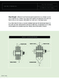
2 The nominal Shear strength (Vn) is composed of the sum of the nominal Shear strength provided by "concrete" (Vc) and the nominal Shear strength provided by Shear reinforcement (Vs). The ultimate nominal Shear strength provided by concrete (Vc) is actually provided by several mechanisms, illustrated in the figure above, including: Shear strength of concrete in compression zone, the vertical component of aggregate interlock, and dowel action of the flexural reinforcement. The ACI code provides two equations for calculating Vc but we will only use one. This is what the author of your text recommends and also it makes Shear Design much simpler. dbfVwcc'2= Flexure cracks Diagonal Tension cracks Shear strength in compression zone vertical component of aggregate interlock Shear reinforcement dowel action of flexural reinforcement CE 433, Fall 2006 Design of Beams for Shear 2 / 7 Shear Reinforcement.
3 Shear reinforcement is oriented perpendicular to the flexural reinforcement. Shear reinforcement can take the form of stirrups (typically used for beams), welded-wire fabric (used for joists), and ties/spiral cages for columns. Shear reinforcement keeps cracks parallel to the flexural reinforcement small. Shear reinforcement that encloses the core of the member (all but WWF) serves to confine the concrete. Confining the concrete in the core has several effects at ultimate strength conditions (concrete is cracked): Friction between pieces of concrete is increased; aggregate interlock increases beam Shear strength . Vertical load capacity of columns is increased by horizontal confinement of concrete by ties and especially by spiral cages.
4 Splitting failure on a horizontal plane through the flexural reinforcement of a beam is reduced. In a Shear failure, the bottom portion of a beam wants to separate from the top. To be effective, Shear reinforcement should be anchored on each end. This can be accomplished by wrapping the stirrup around the longitudinal (flexural) reinforcement on the top and bottom (stirrups) or welding the vertical members to longitudinal bars (WWF). Also, as much of the Shear reinforcement as possible should extend into the compression zone. For these reasons, Shear reinforcement should extend as close to the top and bottom surface of the beams as cover will allow. standard stirrup hook (must enclose a bar) stirrups (typically formed from #3, #4 or #5 bar) welded wire fabric compression zone CE 433, Fall 2006 Design of Beams for Shear 3 / 7 Shear strength of Shear Reinforcement.
5 The Shear strength provided by the Shear reinforcement (Vs) at a section is calculated as follows. Vs = Av fy n Av = cross-section area of one stirrup (both legs) n = number stirrups crossing crack We assume that the diagonal tension crack is at 45o from the vertical. Then the horizontal projected length of the crack = d. So the number of stirrups crossing the crack is: spacingstirrupswheresdnsddscrackbarsn=== =,crackinchesinches everybar one sdfAVyvs= (ACI 11-15) Limits on Shear Reinforcement. The ACI sets several limits regarding Shear reinforcement to ensure that (1) sufficient Shear reinforcement is provided to prevent Shear failure (sufficient Vs), and (2) the Shear reinforcement is distributed so that at least a sufficient number of bars cross the bottom-half of the Shear crack (n bars every d/2).
6 The horizontal projection of the Shear crack from bottom of beam to mid-height is approximately d/2. The designer meets the ACI criteria by specifying two parameters: stirrup size (represented in Equation 11-15 above by the cross-sectional area of the stirrup crossing the Shear crack, Av) stirrup spacing (s) Design Parameters ACI Criteria Stirrup Size (Av) Stirrup Spacing (s) (1) Vs is increased by (2) n bars per d/2 is increased by d s d Vs Vs CE 433, Fall 2006 Design of Beams for Shear 4 / 7 As indicated in the table above, both stirrup size and spacing affect the first criteria (sufficient Vs), but only stirrup spacing affects the second criteria (sufficient number of stirrups crossing the Shear crack).
7 Also, decreasing the spacing improves both the Shear strength (Vs) and the number of stirrups crossing the Shear crack (n bars per d/2). Other stirrup Design criteria (not specified by ACI) are constructability and economy. Stirrups should not be placed closer than 3" or 4" apart so that the contractor can place the concrete between the stirrups. Also, specifying significantly more stirrups than are needed should be avoided. Stirrup Design Equations Stirrup Design typically involves selecting a stirrup size (#3 or #4 are common), and determining the largest spacing that will meet criteria (1) and (2). As the factored Shear force (Vu) increases relative to the concrete Shear strength (Vc), the criteria become more stringent resulting in smaller maximum allowed stirrup spacing.
8 A summary sheet of Shear Design equations presents the maximum allowed stirrup spacing for each range of Vu / Vc. The ACI specifications are presented in the following sections. In each section, the ACI equations are presented and explained, and then rearranged to produce the equations in the Shear Design Equations summary sheet. The first three specifications concern criteria (1) Vs, and the next two specifications concern criteria (2) n / d. 1. Minimum Shear Reinforcement. ACI requires that a minimum amount of Shear reinforcement be provided if the factored Shear is greater than half the Shear capacity of the concrete. min. Shear reinforcement is required if 2cuVV >, or when 21/>cuVV Shear failures are sudden and the predicted Shear strength of a component is highly variable.
9 The minimum Shear reinforcement must provide a minimum Shear force per unit area (dbVvwss=) of cf' or 50psi, whichever is greater. ]50,' [minpsicfvs= The above equation can be expanded and then rearranged to solve for spacing (s) ]50, ['psifdbsdfAdbVvcwyvwss===, or dbpsifdfAswcyv]50, [max'= CE 433, Fall 2006 Design of Beams for Shear 5 / 7 2. Vs of Shear Reinforcement. ACI specifies that when Vu exceeds Vc, then Vs shall be provided so that uscVVV +)( (ACI 11-1, 11-2), or when 1/>cuVV ACI Section specifies Vs (derived above) sdfAVyvs= or cuyvVVdfAs = max 3. Maximum Shear Reinforcement. ACI also requires that the Shear reinforcement provide a Shear force per unit area (vs) of no more than cf'8 This limits the stress in the stirrups and thereby prevents the diagonal cracks from growing too large.
10 Cfvs'8max= The equation above can be expanded and rearranged as follows: 5/max,5max,4max,2'8max,'8max,'= = = == ===cucuccuwccwcucuswxwssVVorVVorVVVdbfVa nddbcfVVsoVVValsodbcfVsodbVv 4. Minimum Number of Stirrups Crossing Bottom-Half of Diagonal Crack. ACI requires that stirrups be placed so that at least one stirrup crosses the Shear crack in the bottom-half of the beam (1 bar per d/2). This corresponds to a maximum spacing of d/2. ]"24,2min[maxds= 5. Minimum Number of Stirrups when dbfVwcs'4>. ACI specifies that when the stirrups must carry large forces (dbfVwcs'4>), the maximum allowable stirrup spacing should be decreased by a factor of 2.