Transcription of Design Note DN038 - TI.com
1 Design Note DN038 SWRA416 Page 1 of 24 Miniature Helical PCB antenna for 868 MHz or 915/920 MHz By Richard Wallace Keywords Miniature Helical PCB antenna Optimized for compact designs 868 or 915/920 MHz ISM Bands CC11xx CC12xx 1 Introduction This document describes a compact PCB helical antenna that has been specifically designed for 868 MHz or 915/920 MHz ISM bands. The PCB helical antenna requires two matching components for matching to a 50-ohm load. When a large PCB area (38 mm x 24 mm) is available for the antenna then the recommended antenna is DN024 [1] since the impedance is closer to 50 ohm without any external matching components (868 MHz: 30+j11; VSWR ) and the bandwidth is around 90 MHz.
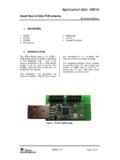
2 The miniature PCB helical antenna is more compact (19 mm x 11 mm) with approximately quarter of the size of the DN024 [1] but requires matching components since the impedance is far from 50 ohms (868 MHz: 10-j88; VSWR 22). When the miniature helical antenna is matched then the bandwidth is around 40 MHz and has similar efficiency as DN024 [1] antenna when measured on the TRXEB platform. All measurement results presented in this document are based on measurements performed on the CC110L EM Rev Reference Design [3], shown in Figure 1.
3 Figure 1. CC110L EM 868 / 915 MHz Design Note DN038 SWRA416 Page 2 of 24 Table of Contents KEYWORDS .. 1 1 INTRODUCTION .. 1 2 ABBREVIATIONS .. 2 3 antenna Design .. 3 PHYSICAL DIMENSIONS .. 3 antenna MATCH NETWORK .. 4 antenna BANDWIDTH 7 antenna OTA MEASUREMENT .. 7 868 MHz OTA Measurement Summary .. 7 4 CONCLUSION .. 9 5 REFERENCES .. 10 6 GENERAL INFORMATION .. 10 DOCUMENT HISTORY .. 10 7 APPENDICES .. 11 CTIA OTA REPORT 868 MHZ ( antenna MATCHED AT 868 MHZ) .. 11 OTA Evaluation Results .. 11 .. 12.
4 13 .. 14 Theta = 0, Phi = 0 .. 15 Theta = 180, Phi = 0 .. 15 Theta = 90, Phi = 0 .. 16 Theta = 90, Phi = 180 .. 16 Theta = 90, Phi = 270 .. 17 Theta = 90, Phi = 90 .. 17 CTIA OTA REPORT 915 MHZ ( antenna MATCHED AT 868 MHZ) .. 18 OTA Evaluation Results: .. 18 .. 19 .. 20 .. 21 Theta = 0, Phi = 0 .. 22 Theta = 180, Phi = 0 .. 22 Theta = 90, Phi = 0 .. 23 Theta = 90, Phi = 180 .. 23 Theta = 90, Phi = 270 .. 24 Theta = 90, Phi = 90 .. 24 2 Abbreviations ANT antenna CTIA Cellular Telephone Industry Association DC Direct Current EM Evaluation Module ETSI European Telecommunications Standards Institute FCC Federal Communications Commission FR4 Material type used for producing PCB ISM Industrial, Scientific, Medical NM Not Mounted OTA Over The Air PCB Printed Circuit Board SRD Short Range Devices TRP Total Radiated Power TRXEB Evaluation Board Design Note DN038 SWRA416 Page 3 of 24 3 antenna Design Physical Dimensions Figure 2.
5 Top Layer Layout Figure 3. Zoom of Top and Bottom Layer Layout with Via Markings Dimension H H1 H2 W W1 W2 Via dia 12 mm 6 mm mm 19 mm 1 mm 1 mm mm Table 1. antenna Dimensions Top layer is shown in blue and the bottom layer is shown in red for Figure 2 and Figure 3. The X markers indicate via positions which route between the top and bottom layers. PCB board thickness for the CC110L EM 868 / 915 MHz reference Design [3] is mm. Another PCB thickness can be used but then the antenna match must be re-calculated. Design Note DN038 SWRA416 Page 4 of 24 Dimensions for the antenna can be found in Table 1 and the gerbers for the antenna Design are also available for 868/915 MHz [3] antenna Match Network There are several ways to tune an antenna to achieve better performance.
6 For resonant antennas the main factor is the length. Ideally the frequency which gives least reflection should be in the middle of the frequency band of interest. Thus if the resonance frequency is too low, the antenna should be made shorter. If the resonance frequency is too high, the antenna length should be increased. Even if the antenna resonates at the correct frequency it might not be well matched to the correct impedance. Size of ground plane, distance from antenna to ground plane, dimensions of antenna elements, feed point and plastic casing are factors that can affect the impedance.
7 Since the impedance will change depending on several parameters; with a pi-network as illustrated in Figure 4, the antenna match can always be restored to a 50 ohm match. Only two of the components (ANT2 + (ANT1 or ANT3) ) are required to match the impedance to 50 ohm depending on the start impedance. For the PCB helical antenna at 868 / 915 MHz, only ANT2 and ANT3 are required. Figure 4. antenna Match Network Design Note DN038 SWRA416 Page 5 of 24 Figure 5. Start Impedance with 0-ohm (ANT2) Resistor in antenna Match The impedance of the PCB helical antenna is far from 50 ohm without the antenna matching network so the matching network acts as a load and matching network for the antenna .
8 The impedance of the antenna can be seen in Figure 5 when ANT2 is set to 0 ohm. Figure 6 shows the theoretical load and match to at 868 MHz. The Smith diagram shows a shunt component of nH (ANT3) and a series capacitor of pF (ANT2). ANT1 component is not required and can be left open. nH value does not exist so a 12 nH is used instead. Design Note DN038 SWRA416 Page 6 of 24 Figure 6. Theoretical antenna Match Assembling ANT2 ( pF) and ANT3 (12 nH) based on the theoretical calculated match, then the impedance can be re-measured and a good match is measured and can be seen in Figure 7.
9 Figure 7. With antenna Match Components - ANT2: pF and ANT3: 12 nH Design Note DN038 SWRA416 Page 7 of 24 antenna Bandwidth Measurement Figure 8. Bandwidth Measurement at VSWR 2 As can be seen from Figure 8, the bandwidth is 40 MHz with a VSWR 2 and 68 MHz with a VSWR 3. antenna OTA Measurement The conducted output power from the radio is 0 dBm and the results shown in section show the performance of the antenna of the CC110L EM 868 / 915 MHz on the TRXEB platform. 868 MHz OTA Measurement Summary Total Radiated Power dBm Peak EIRP dBm Directivity dBi Efficiency dB Efficiency % Gain dBi NHPRP 45 dBm NHPRP 45 / TRP dB NHPRP 45 / TRP % NHPRP 30 dBm NHPRP 30 / TRP dB NHPRP 30 / TRP % NHPRP dBm NHPRP / TRP dB NHPRP / TRP % UHRP dBm UHRP / TRP dB UHRP / TRP % Design Note DN038 SWRA416 Page 8 of 24 LHRP dBm LHRP / TRP dB LHRP / TRP % Front/Back Ratio PhiBW deg PhiBW Up deg PhiBW Down deg ThetaBW deg ThetaBW Up deg ThetaBW
10 Down deg Boresight Phi 90 deg Boresight Theta 15 deg Maximum Power dBm Minimum Power dBm Average Power dBm Max/Min Ratio dB Max/Avg Ratio dB Min/Avg Ratio dB Best Single Value dBm Best Position Phi = 45 deg; Theta = 165 deg; Pol = Ver For the full CTIA report including 3D radiated plots at 868 MHz please refer to section The antenna was also measured at 915 MHz to show the performance degradation whilst keeping the same matching network at 868 MHz; this is shown in section For optimum performance at 915 MHz, the antenna needs to be re-matched at this frequency.