Transcription of Development of High Efficiency Miller Cycle Gas …
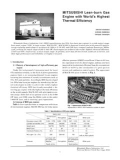
1 146. Development of high Efficiency Miller Cycle Gas engine Yorihiro Fukuzawa*1 Hiromi Shimoda*1. Yoshitaka Kakuhama* 1 Hiroyuki Endo*2. Kengo Tanaka*2. Gas engine cogeneration is gaining popularity, due to its high Efficiency and low exhaust emission. Recent technological progress in gas engines and gas turbines has led to high generating Efficiency . As the advantages of cogeneration have become more widely recognized by customers with comparatively low demands for heat, it has become more widely used in a variety of fields. This trend is expected to accelerate and further improvement in generating Efficiency of gas engines is an urgent task. Mitsubishi Heavy Industries, Ltd. and Osaka Gas Co., Ltd. have jointly applied the Miller Cycle to a lean-burn gas engine , developing the world's first gas engine in this class to achieve 40% generating Efficiency .
2 The 280 kW engine was commercially released in April 2000. engine , however, the increase of the compression ra- 1. Introduction tio raises the cylinder gas temperature. This causes The output of gas engines for cogeneration mainly knocking due to the auto-ignition of unburnt gas be- ranges from 100 to 1 000 kW. The present gas engines fore the flame reaches the end gas area, causing the are broadly classified in two types: lean-burn system (1) temperature and pressure inside the cylinder to rise and stoichiometric air-fuel ratio combustion system, sharply until the engine gets damaged (broken). In with the lower output engines using the stoichiomet- order to prevent this, it is necessary to delay the ig- ric air-fuel ratio combustion system while the medium nition timing, but delaying the ignition timing leads and large size engines adopting the lean-burn sys- to the reduction of the degree of constant volume of tem.
3 The lean-burn system generally features in high combustion (the index including the degree of effi- generating Efficiency and low NOx emission in addi- ciency reduction against the constant volume tion to the excellent endurance of the low-tempera- combustion Cycle ), nullifying the effect of high theo- ture combustion flame. retical Cycle Efficiency . Miller Cycle was presented by Mitsubishi Heavy Industries, Ltd. (MHI) and Miller (2) as a Cycle to solve the aforesaid problems. In Osaka Gas Co., Ltd. have jointly applied the Miller the case of a conventional reciprocating internal com- Cycle to a lean-burn gas engine to develop the world's bustion engine the inlet valve close timing and the first gas engine in this class with the generating effi- exhaust valve open timing are adjacent to the bottom ciency standing at 40%.
4 With the 280 kW engine dead center (BDC), and the compression ratio is released commercially in April 2000 after having nearly equivalent to the expansion ratio. In the Miller cleared the endurance test over 4 000 hours, this pa- Cycle , the effective close timing of the inlet valve is per describes the main technologies and performance slightly shifted forward or backward from the bottom specifications for this engine as well as for the series dead center to decrease only the effective compres- of engines planned in the future. sion ratio, making expansion ratio > compression ratio. In the case of an internal combustion engine 2. Elementary technology with expansion ratio > compression ratio, the com- This section deals with the applied elementary pression ratio in equation (1) can safely be used as technologies and developments.
5 The expansion ratio. In other words, by applying the Application of Miller Cycle Miller Cycle , the compression ratio can be kept to a The theoretical Cycle Efficiency in a conventional level that prevents knocking, while keeping the ex- Cycle internal combustion engine with nearly equiva- pansion ratio at a high level to ensure high Efficiency . lent compression ratio and expansion ratio is Quite a few researches and developments have so expressed by equation (1). far been made on the application of Miller Cycle , with theory = 1- 1- (1) a few of them already commercialized (3)-(5) . In each where, case, however, the stoichiometric air-fuel ratio com- : engine compression ratio ( expansion ratio) bustion system engine with low thermal Efficiency has : adiabatic index of working fluid basically been used, so that the Miller Cycle has so This indicates that it is necessary to increase the far not been used for commercialization at the ther- compression ratio in order to improve the theo- mal Efficiency exceeding 40% level.
6 In our retical Cycle Efficiency . In the case of a natural gas Development program, we applied Miller Cycle basi- *1 General Machinery & Special Vehicle Headquarters Mitsubishi Heavy Industries, Ltd. *2 Nagasaki Research & Development Center, Technical Headquarters Technical Review (Oct. 2001). 147. cally for lean-burn gas engines with pre-chamber sys- maximum advance ignition timing and inlet manifold tem having a high thermal Efficiency of 37%, aiming pressure. Excessively high effective compression ra- at a thermal Efficiency of (at a generating effi- tio causes knocking calling for delay in ignition ciency of 40%). We set up a target in our Development timing, which causes the thermal Efficiency to get re- program using simulation, etc.
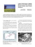
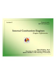
7 In order to raise the duced. On the other hand, excessively low effective conventional engine thermal Efficiency from 37% to compression ratio causes the pressure ratio required The Development program proceeded putting for the turbocharger to get excessively high . Thus, the target to getting the thermal Efficiency improved from the test result in Fig. 2 we selected the inlet by 3% or over by improving the theoretical Cycle effi- valve close timing that provides the effective compres- ciency through the set expansion ratio/compression sion ratio of 11. ratio, and the remaining by improving the de- Improvement in combustion performance gree of constant volume of combustion and combustion In the case of a Miller Cycle gas engine the com- Efficiency and by reducing the heat loss and pumping bustion chamber volume at compression top dead loss.
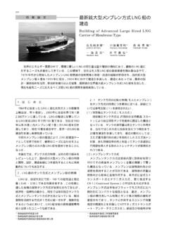
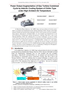
8 Center (TDC) is reduced because of the high expan- Setting of expansion ratio/compression ratio sion ratio. This causes the combustion Efficiency to First of all we studied the expansion ratio and com- get reduced, nullifying the effect of high expansion pression ratio through performance calculation (6) , ratio, and inversely reducing the Efficiency . The ma- paying attention to the pulsation inside the inlet and jor problem in this Development program was to exhaust pipes, and grasped the appropriate values. ensure combustion Efficiency equivalent to or higher Fig 1 shows the relation between expansion ratio and than that of a conventional gas engine at a smaller estimated thermal Efficiency , indicating obviously volumetric space. Hence, we developed the main that the engine thermal Efficiency of 40% can be chamber shape using a single cylinder test engine achieved by setting the expansion ratio (compression shown in Table 1, the optimization of inlet air swirl ratio based on bottom dead center) to 15.
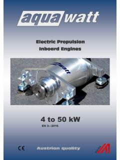
9 Thus, the ratio, and pre-chamber specification. expansion ratio based on the calculation result was (1) Main (combustion) chamber shape set to 15. Further, the inlet valve close timing was As for the shape of the main (combustion) cham- experimentally set. Fig 2 shows the relation between ber, two types were tested. One was a high turbulence the actually measured effective compression ratio (es- type, aiming at increasing combustion speed through timated from the relation between boost pressure and enhanced turbulence speed inside the combustion compression pressure) using a six-cylinder test en- chamber, and the other was a low unburnt type, aim- gine shown in Tablablee 1 and the thermal Efficiency at ing at reducing the unburnt gas by reducing the top clearance section.
10 The test results are shown in Fig 3 . 43 It is obvious from the figure that the low unburnt type engine thermal Efficiency (%). 42. Boost pressure (Relative value). 41. 40. 39. 38. 37. 1. 36. 10 11 12 13 14 15 16 17 engine thermal Efficiency (%). Expansion ratio Fig. 1 Relation between expansion ratio and thermal Efficiency (calculation results). Thermal Efficiency is improved by 3% through the enhanced expansion ratio to 15. Table 1 Test engine specifications Number of cylinders 1 6 Cylinder diameter (mm) 170 11 12 13 Stroke (mm) 180. Break mean effective (MPa) Effective compression ratio pressure (BMEP) Fig. 2 Relation between effective compression ratio, and engine speed (min-1) 1 200/1 800 thermal Efficiency and supercharging pressure Outside Exhaust (test results from six cylinder engine ).