Transcription of Power Output Augmentation of Gas Turbine …
1 mitsubishi heavy Industries technical review Vol. 47 No. 4 (December 2010) 33 *1 Manager, Centrifugal & Absorption Chiller Department, Air-Conditioning & Refrigeration Systems Headquarters *2 Manager, Takasago Research & Development Center, technical Headquarters *3 Manager, Service Department, Takasago Machinery Works *4 Service Department, Takasago Machinery Works Power Output Augmentation of Gas Turbine Combined Cycle by Inlet-Air Cooling System of Chiller Type under High Ambient Air Temperature TAKANOBU KOMURO*1 EISAKU ITO*2 TAKASHI SONODA*2 YASUOKI TOMITA*3 KOHEI HIDAKA*4 SEIJI SHIBUTANI*1 At mitsubishi heavy Industries, Ltd.
2 (MHI), large-scale gas turbines for electric Power plants are designed and manufactured at the Takasago Machinery Works. Because of the highly advanced design and manufacturing technologies used for turbo machines and heat exchangers, large-capacity, high-efficient centrifugal-chillers are also designed and manufactured at the Air-Conditioning & Refrigeration Systems Headquarters Takasago Plant that is part of the Takasago Machinery Works. By combining these two product technologies, an inlet-air cooling system with a gas- Turbine inlet section has been developed for gas Turbine combined cycle Power plants (GTCC).
3 For refrigeration equipment, a centrifugal-chiller, cooling tower, water supply pump and Power supply unit are packaged in a single unit. An inlet-air cooling coil unit placed in an air-inlet duct is devised so as to be installed during the major inspection period of gas turbines. Our Power Systems Headquarter and Air-Conditioning & Refrigeration Headquarter are integrated to provide one-stop services for our customers. |1. Introduction At mitsubishi heavy Industries, Ltd. (MHI), large-scale gas turbines for electric Power plants are designed and manufactured at the Takasago Machinery Works.
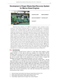
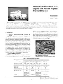
4 Because of the highly advanced design and manufacturing technologies used for turbo machines and heat exchangers, large-capacity, high-efficient centrifugal-chillers are also designed and manufactured at the Air-Conditioning & Refrigeration Systems Headquarters Takasago Plant that is part of the Takasago Machinery Works. By combining these two product technologies, an inlet-air cooling system with a gas- Turbine inlet section has been developed for gas Turbine combined cycle Power plants (GTCC). The relationship of the Output Power of a gas Turbine the core of a combined cycle Power plant to ambient air temperature is shown in Figure 1.
5 Figure 1 Power - Output recovery mechanism by inlet-air cooling system in gas Turbine combined cycle Power plant (GTCC) Air density increases by lowering inlet-air temperature, contributing to Power Output recovery. mitsubishi heavy Industries technical review Vol. 47 No. 4 (December 2010) 34 In a gas Turbine , atmospheric air is suctioned, compressed, mixed with fuel and burned in a combustor to generate electricity. The air density falls as the ambient air temperature rises, suchthat the Power Output decreases depending on the decrease in the mass of air that is sent to thecombustor.
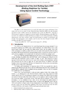
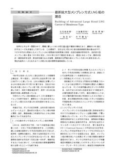
6 When air at a temperature of 35 C is cooled to 15 C, the air density increases by about 10 percent, increasing the Power Output by about 10 percent. |2. Inlet-air cooling system Cooling mechanism of centrifugal-chiller Figure 2 shows the cooling mechanism of the centrifugal-chiller. The cooling mechanisms are as follows: (1) A refrigerant gas contained in the top section of an evaporator under conditions below 10 C and around MPa is compressed by a turbo (centrifugal) compressor and sent to a condenser, with the conditions of the gas over 40 C and around 1 MPa. (2) In a wet cooling tower (one example here, but many other methods of heat exchange are known), cooling water at around 30 C that has been heat-exchanged with atmospheric air is sent to the above condenser and again heat-exchanged with the refrigerant, liquefying the refrigerant.
7 (3) The high pressure liquefied refrigerant in the condenser is adiabatically expanded to the evaporator via an expansion valve, resulting in a low pressure liquefied refrigerant at a single-digit temperature level. (4) In an evaporator, the low pressure liquefied refrigerant is heat-exchanged with the returned cooling water at 10-some C from the cooling coil, returning the refrigerant to a gaseous condition and where the cooling water is cooled to a single-digit temperature (for instance, 5 C). MHI s centrifugal-chiller has a feature that can provide cold energy corresponding to times the electric Power for the drive motor of a compressor to a cooling coil, which is referred to as a coefficient of performance (COP) of Figure 2 Cooling mechanism of centrifugal-chiller Comparison of inlet-air cooling system Table 1 shows a comparison of general inlet -air cooling systems.
8 Inlet-air cooling systems include: (a) An eva-cooler system in which air is cooled with the latent heat of water vaporization by dripping water from evaporative elements placed in the downstream of an air-inlet filter housing in an air-inlet duct inlet portion. (b) A fog system in which air is cooled with the latent heat of water vaporization by atomizing water mist in the downstream of an air-inlet filter housing. (c) A chiller system in which air is cooled by introducing chilled water from a chiller such as a centrifugal-chiller into a cooling coil placed in the downstream of an air-inlet filter housing.
9 In this development of the cooling system, a chiller system that can lower the temperature of the inlet air below a wet-bulb temperature, which results in a greater increase rate, has beenselected. mitsubishi heavy Industries technical review Vol. 47 No. 4 (December 2010) 35 Table 1 Comparison of inlet air cooling systems Eva-cooler system Fog system Chiller system System outline Inlet-air cooling with the latent heat of water by dripping water from evaporative elements of an eva-cooler Inlet-air cooling with the latent heat of water by atomizing water mist Inlet-air cooling by introducing chilled water from a chiller such as a centrifugal-chiller into a cooling coil placed in the downstream of an inlet-air filter housing System configuration Inlet-air temperature drops approx.
10 5 C (atmospheric conditions: 30 C, RH: 60%) approx. 5 C (atmospheric conditions: 30 C, RH: 60%) approx. 15 C (atmospheric conditions: 30 C) Output recovery rate approx. 3% approx. 3% approx. 9% Features (1) Air temperature is not attained below a wet-bulb temperature, so that the effect of system is small in high humidity conditions. (2) A mist eliminator is required. (1) Drainage system is required in an inlet air duct. (2) Air temperature is not attained below a wet-bulb temperature, so that the effect of system is small in high humidity conditions.