Transcription of Advancement of Compressor Plant Training …
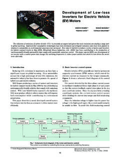
1 Mitsubishi Heavy Industries, Review (Jun. 2001)57 Advancement of Compressor Plant Training SimulatorSusumu Kouno*1 Kenji Suzuki*1 Susumu Izaki*2 Sumio Noda*3 Hajime Hiromoto*4*1 Hiroshima Research & Development Center, Technical Headquarters*2 Machinery Headquarters*3 Hiroshima Machinery Works*4 MHI Turbo Techno have accepted over 1 600 trainees since opening the Turbo Machinery Training Center in Hiroshima MachineryWorks of Mitsubishi Heavy Industries, Ltd. (MHI). As a part of Training program, the simulator has been utilized foreffective operation Training . However, since it became old fashioned, we developed an advanced Compressor planttraining simulator in order to comply recent control system s requirements. The new simulator features (1) a steamturbine model operated by electronic governor, (2) real DCS control and CRT operation, and (3) Training capability indry-gas seal system and gas turbine drive Compressor Introduction1.
2 Introduction1. Introduction1. Introduction1. IntroductionBecause of the high reliability of the component ma-chines, the Compressor plants have recently come to beoperated continuously over a long time. As a result, theoperators have fewer chances to practice such Plant op-erations as start/stop, and emergency programs using simulator similar to theactual machines have, therefore, become increasinglynecessary in order to maintain and improve the skill ofthe have so far accepted a large number of traineesfrom our customers in Japan and abroad in the TurboMachinery Training Center in MHI Hiroshima Machin-ery Works ever since the center was established, andthe effective Training programs there using the train-ing simulator have gained high , with the equipment becoming outdated andbecause of the Advancement made in Compressor planttechnology, we had to develop a more sophisticated train-ing main functions newly added to the simulator aregiven below.
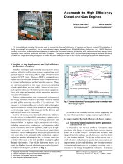
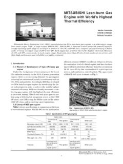
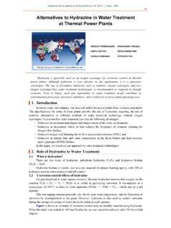
3 (1) Adoption of digital control unit(2) Correspondence with Training for dry gas seal sys-tem(3) Correspondence with gas turbine driven Compressor (4) Installation of steam turbine model operated by elec-tronic governor similar to the actual equipmentFig. 1 Fig. 1 Fig. 1 Fig. 1 Fig. 1 shows the appearance of the new Training simu-lator paper introduces the configuration, main func-tions, operational form etc. of the new Training Corresponding Process2. Corresponding Process2. Corresponding Process2. Corresponding Process2. Corresponding ProcessThe Compressor Plant Training simulator is de-signed mainly for the operational Training of the gasprocess using centrifugal Compressor , the driver, thelubricating oil system, and seal system treated as aproduct in MHI Hiroshima Machinery Works. TTTTT ablablablablableeeee11111shows the systems and component machines for simu-Fig.
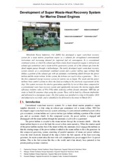
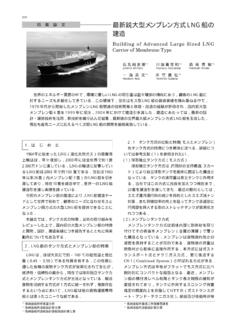
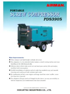
4 1 Compressor Plant Training simulatorFig. 1 Compressor Plant Training simulatorFig. 1 Compressor Plant Training simulatorFig. 1 Compressor Plant Training simulatorFig. 1 Compressor Plant Training simulatorThe appearance of steam turbine model and graphic panel of Compressor planttraining simulator equipment is Heavy Industries, Review (Jun. 2001)58lation. It is possible to select make-up gas process/refrigeration process in the gas process, steam tur-bine/gas turbine/electric motor in the driver, and oilfilm seal system/dry gas seal system in the seal sys-tem. As shown in Fig. 2 Fig. 2 Fig. 2 Fig. 2 Fig. 2, these can be combined toenable the simulation of eight different patterns ofplant configuration. This time, gas turbine and drygas seal system were newly added. Because of theenhanced reliability, gas turbines have recently cometo be increasingly adopted as drivers.
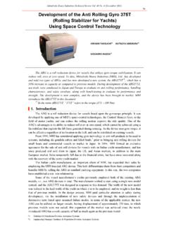
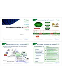
5 Further, the drygas seal system has become the mainstream becauseof the advantages such as: easy operation, less gasleakage, no contamination of process gas due to oil,and small number of component machines leading tolow cost and easy System Configuration3. System Configuration3. System Configuration3. System Configuration3. System ConfigurationNext, the configuration of the Training simulator sys-tem is described 33333 shows the Training simulator system configu-ration.(1) Graphic panelIt is a large panel with the machines and pipingdiagrams drawn on it, and the field measuring in-struments, lamps, snap switches, volume switchesand others installed to enable operational simulationof field machines. Simulation is carried out by ON/OFF operation of the snap switches for valves oper-ated either at OPEN or CLOSE mode, and by usingvolume switches for the manual control valves need-ing partial opening.
6 Actual one-loop controllers areinstalled as field controllers enabling Training forauto/manual adjustment of the control signal andadjustment of control parameters. It is possible tocarry out simulation of the field equipment opera-tion of five systems: make-up gas process (G1),refrigeration process (G2), steam turbine system (G3),lubricating oil and oil film seal system (G4) and newlyadded dry gas seal system (G5).(2) Field instrument panelThe field instrument panel is equipped with theswitches for manual stop of the Compressor driver andstart/stop of the turning motor, process value indica-tors and alarm display devices.(3) Steam turbine modelThe steam turbine model is a model for steam tur-bine control mechanism. Similar to the actual Plant ,it is composed of the trip and throttle valve (TTV),governing valve (GV), extraction control valve (ECV),control lever, and solenoid valve for trip, etc.
7 And isdriven by electro-hydraulic actuator and link usingFig. 2 Compressor process pattern selectionFig. 2 Compressor process pattern selectionFig. 2 Compressor process pattern selectionFig. 2 Compressor process pattern selectionFig. 2 Compressor process pattern selectionThe mesh sections are the newly developed parts,allowing 8 patterns of Plant configuration processSeal systemMake-up gas processRefrigeration process Steam turbineGas turbineElectric motorOil film sealDry gas sealDriverTable 1 Simulated process equipmentTable 1 Simulated process equipmentTable 1 Simulated process equipmentTable 1 Simulated process equipment System classification System name Abbreviation of system name System outline Machines for modeling Make-up gas process G1 Cracked gas five-stage compression Compressor , gas cooler, gas separator, etc. Gas process Refrigeration process G2 Propylene side stream type Compressor Compressor , suction drum, cooler, receiver, etc.
8 Steam turbine system G3 Extraction condensing turbine with electronic governor Turbine, condenser, ejector, condenser pump (steam turbine driven, motor driven), trip and throttle valve (TTV), governing valve (GV), extraction pressure control valve (ECV), turning motor, process trip circuit, etc. Electric motor system GM Electric motor Electric motor Driver Gas turbine system* GT Gas turbine Gas turbine Lubricating oil system Lubricating oil system G4 (Partial) Lubricating oil for Compressor and driver Oil reservoir, lubricating oil pump (steam turbine driven/motor driven), oil filter, etc. Oil film seal system G4 (Partial) Supply of seal oil (high-pressure, middle-pressure, low-pressure) Oil cooler, seal oil pump (steam turbine driven/motor driven), oil filter, seal oil head tank, oil trap, etc. Seal system Dry gas seal system* G5 Seal gas and separation gas Gas seal, gas filter, seal differential pressure control valve *: newly developed item.
9 Mitsubishi Heavy Industries, Review (Jun. 2001)59control oil as in the case of an actual machine. TheEH actuator operates due to control signal of the elec-tronic governor, with the lift value fed back to thehost computer through the process controller to beused in the calculation of steam turbine rotationalspeed, and extraction flow.(4) Electronic governorThe electronic governor used here is similar to thatused in an actual Plant . It receives the process val-ues such as steam turbine speed, extraction pressurefrom the host computer before transmitting the con-trol signals to the EH actuators of GV and ECV. Itenables the lever set adjustment Training for main-tenance personnel in addition to the operationtraining of electronic governor.(5) Operator stationThe operator station is equivalent to the one in-stalled in the central control room in an actual Plant ,enabling CRT touch operation.
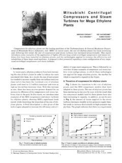
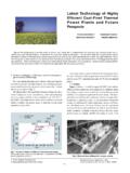
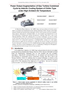
10 The station is capableof displaying the monitoring and operating screens,controller screen, alarm monitoring screen, interlockmonitoring screen, historical trend screen, compres-sor performance curve screen, etc. The examples ofmake-up gas process and dry gas seal system moni-toring screens are shown in and (6) Process controllerA digital process controller similar to the oneadopted in an actual Plant is used here. It receivesthe operation signals of valves, pumps, etc. of the fielddevices such as graphic panel, field instrument panel,Fig. 3 Configuration of Compressor Plant Training simulator systemFig. 3 Configuration of Compressor Plant Training simulator systemFig. 3 Configuration of Compressor Plant Training simulator systemFig. 3 Configuration of Compressor Plant Training simulator systemFig. 3 Configuration of Compressor Plant Training simulator systemThe connection of machines in the Compressor Plant Training simulator equipment is 4 Make-up gas process monitoring graphic display inFig.