Transcription of Digital Isolator Design Guide (Rev. A) - Texas …
1 Developer's GuideSLLA284A January2009 RevisedNovember2014 DigitalIsolatorDesignGuideThisdesignguid ehelpssystemdesignersof galvanicallyisolatedsystemsto begindesigningwith TI'sbroadportfolioof digitalisolatorsandisolatedfunctionsin the ISO78xxfamilyof ,the ISO73xxfamilyof 3-kVrmsdigitalisolators,and the ISO71xxfamilyof , documentexplainsthebasicoperatingprincip leof an Isolator ,suggestswhereto placeit withina systemdesign,andrecommendsguidelinesfor an electromagneticcompatible(EMC) availablein the respectiveproductdatasheetsand the (OOK) DigitalIsolatorsand of Figures1 ConceptualBlockDiagramof On-OffKeying(OOK) a.
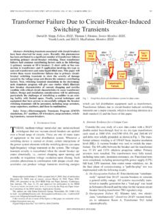
2 Z0~ a Functionof the w/h a January2009 RevisedNovember2014 DigitalIsolatorDesignGuideSubmitDocument ationFeedbackCopyright 2009 2014, 45 BendsInsteadof 90 a Singleand a a Singleand a a of Tables1 DigitalIsolatorFamiliesand < w/d < a meansof preventingdc and unwantedac currentsbetweentwo partsof a system,whileallowingsignaland powertransferbetweenthosetwo semiconductorICsusedfor isolationare general,an isolatorcan be abstractedas comprisingof a high-voltageisolationcomponentor barrier,a transmitter(TX)to couplesignalinto one side of the isolationcomponent,and a receiver(RX)to convertthe signalavailableon the otherside of the isolationcomponentinto 's isolatorsuse SiO2(silicondioxide)based,high-voltageca pacitorsto serveas the the TX and RX circuits,two differentarchitecturesare used:Edgebasedand On-OffKeying(OOK) explainedin and conceptualblockdiagramof edge-basedcommunicationis shownin Figure1.
3 The isolatorsofISO73xx,ISO74xx,ISO71xx,ISO76 xx,ISO75xx,and ISO72xxfamiliesuse this architecturein deviceconsistsof at leasttwo datachannels,a high-frequencychannel(HF)with a bandwidthfrom100kbpsup to 150 Mbps,and a low-frequencychannel(LF) coveringthe rangefrom100kbpsdownto principle,a single-endedinputsignalenteringthe HF-channelis split into a differentialsignalvia theinvertergateat the followingcapacitor-resistornetworksdiffe rentiatethe signalinto smallandnarrowtransients,whichthenare convertedinto rail-to-raildifferentialpulsesby two NOR-gateflip-flopwhoseoutputfeedsan decisionlogic(DCL)
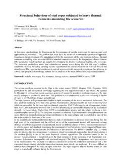
4 At the drivingoutputof the flip-flopmeasuresthe the durationbetweentwo consecutivetransientsexceedsa certaintime limit (as in the caseof a low-frequencysignal)the DCLforcesthe output-multiplexerto switchfromthe high-frequencyto the internalcapacitorsto assumeprohibitivelylargevalues,thesesign alsare pulse-widthmodulated(PWM)with the carrierfrequencyof an internaloscillator,thuscreatinga sufficientlyhigh frequency,capableof passingthe the inputis modulated,a low-passfilter (LPF)is neededto removethe high-frequencycarrierfromthe actualdatabeforepassingit on to the January2009 RevisedNovember2014 SubmitDocumentationFeedbackCopyright 2009 2014,TexasInstrumentsIncorporatedSiO2 BasedCapacitiveIsolationBarrierOscillato rSpreadSpectrumOOKM odulationTX Signal ConditioningRX Signal ConditioningPre-ampEnvelopeDetectorTX INRX ConceptualBlockDiagramof (OOK)BasedCommunicationThe conceptualoperationof OOK-basedcommunicationis shownin Figure2.
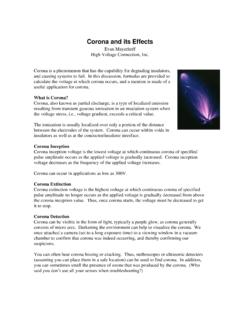
5 The correspondingsignalingis shownin Figure3. The isolatorsin the ISO78xxfamilyuse this this architecture,the incomingdigitalbit streamis modulatedwith an internalspreadspectrumoscillatorclockto generateOOKsignaling,suchthat one of the inputstatesis representedby transmissionof acarrierfrequency,and the otherstateby no modulatedsignalis coupledto the isolationbarrierand appearsin an attenuatedformon the receivepathconsistsof a pre-amplifierto gain up the incomingsignalfollowedby an envelopedetectorthat servesas a demodulatortoregeneratethe TX and RX signalconditioningcircuitsare usedto improvethecommonmoderejectionof the channelresultingin betterCommonModeTransientImmunity(CMTI).
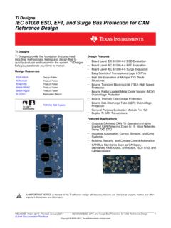
6 Figure2. ConceptualBlockDiagramof On-OffKeying(OOK)Architecture3 SLLA284A January2009 RevisedNovember2014 DigitalIsolatorDesignGuideSubmitDocument ationFeedbackCopyright 2009 2014,TexasInstrumentsIncorporatedGND1 INDVcc1 GND2 OUTDINBEN1 GND2 OUTCVcc212341615141356781211109 ISOLATIONINAGND1EN2 OUTBOUTAINCTX INRX OUTS ignal ThroughIsolation ChannelTypicalApplicationsfor DigitalIsolatorsand RepresentativeSignalin OOKA rchitecture2 TypicalApplicationsfor DigitalIsolatorsand IsolatedFunctionsFigure4. ExampleIsolatorin a 16-PinPackageA pin diagramof a typicaldigitalisolatoris shownin Figure4.
7 It consistsof two supplies:VCC1and VCC2,two grounds:GND1and GND2,and inputand outputpins on eitherside referredto the , in Figure4, pins 1 through8 are referredto GND1and pins 9 through16 are single-ended,CMOSor TTL logic, voltagerangenormallyranges3 V to V for bothsupplies,VCC1and VCC2, thoughsomedevicesmay supporta example,ISO78xxdevicescan workwith suppliesdownto Whendesigningwith digitalisolators,it is importantto keepin mindthat due to the single-endeddesignstructure,digitalisola torsdo not conformto any specificinterfacestandardand are only intendedfor deviceswhereadditionalfunctionality,such as a transceiveror a gate-driverisintegratedalongwith an exampleis the integratedisolated-RS485describedlateron in ,an isolatedfunctionmay needto conformto ,an isolated-I2C bufferwill be compatibleto the I2C ,an isolatedfunctionmay runoff highersupplies,for example.
8 An isolatedgate-drivermay use 15 V to be able to drivean requiredin modernelectricalsystemsfor a varietyof to protecthumanoperatorsfromhigh voltagetransientsand preventingdamageto expensiveprocessors,ASICsorFPGAsin high-voltagesystems,breakingthe groundloop in communicationnetworksand communicationto high-sidedevicesin motordriveor applicationsthat needisolationincludeindustrialautomation systems,motordrives,medicalequipment,sol arinverters,powersupplies,and hybridelectricvehicles(HEV).Someexamplea pplicationsof digitalisolatorsand isolatedfunctionsare presentedin this ,detailedapplicationdiagramsand use cases,pleasereferthe January2009 RevisedNovember2014 SubmitDocumentationFeedbackCopyright 2009 2014.
9 TexasInstrumentsIncorporatedRXIsolationI solation5 VISO5 VISO3V3V3V5 VISO+12V-12 VTX/RTS/DTR/DSR/CD/CTS/RID0 D7/IOR/IOWINTRESETA0A1A2 MEMR or I/ORD0 D7 MEMW or I/OWINTRRESETA0A1A2 CPU BUSRXTX/RTS/DTR/DSR/CD/CTS/RI1596 UARTRS 232 Drivers & DigitalIsolatorsand IsolatedFunctionsFigure5 presentsthe entirecircuitconstitutesa single-ended,low-voltagesystemin whicha digitalisolatorconnectsthe SPI interfaceof a controllerwith the SPIinterfaceof a mostcommonlyappliedisolatorsin SPI interfacesare ISO7x31andISO7x41,henceoftendesignatedas 3- and 4-channelSPI IsolatedSPI InterfaceThe full-blown,isolatedRS-232interfacein Figure6 requirestwo quadisolatorsdue to the six controlsignalsrequiredin additionto the actualdatalines,RX and TX.
10 Althoughthe entiresystemis single-ended,the high-voltagerequirementsof the symmetric,13-Vbus supplymakeit necessaryto galvanicallyisolatethe datalink betweenthe UARTand the low-voltageside of the bus ,the 13-Vdcbus may be in turn generatedfroma highersupply,in whichcasethe isolationalso servesas a meansofprotectionagainsthigh-voltagetran sientson the IsolatedRS-232 Interface5 SLLA284A January2009 RevisedNovember2014 DigitalIsolatorDesignGuideSubmitDocument ationFeedbackCopyright 2009 2014, in the examplein Figure6, the isolationof the RS-485interfacein Figure7 occursbetweenthecontrollerand the bus entireinterfacecircuitbeinga low-voltsystem,thedifferentialnatureof the transmissionbus requirespriorisolationon the a multi-nodedistributedRS-485network,diffe rentnodesmay be referencedto groundsat differentpotential,in whichcaseisolationenablescommunicationby IsolatedRS-485 InterfaceDue to the simplicityof the interfaceshownin Figure8, it is po