Transcription of Digital Power Plugs for Proportional Valves - Eaton
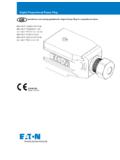
1 Digital Power Plugs for Proportional ValvesEHH-AMP-702/12 C/D/K/G/N/P SeriesFor use with valve types: KDG4V-3(S)-H*-6* KTG4V-3(S)-H*-6* KDG4V-5-H*-3* KTG4V-5-H*-3* KCG-3/6/8-H1-1* KX(C)G-6/8-H1-1* KDG5V-5/7/8-H1-1* CMX**-E-G EPV* ERV* EPRV* ESV* EFV* IRV* PFR21* PFR24* PDR21* PPD22*Model code descriptionEHH-AMP-7aa-b-c-d-e-30aa Supply voltage12 12V version (8 to 16V)02 24V version (18 to 32V)b Analog command inputC Soft switch (12V ON, 5V OFF)D 0 to 10VK 4 to 20mAG 0 to 5V or JoystickN No command input (software/CAN/SWD-DT command)P Peak and Holdc Digital communicationC CAN OpenR RS232S SmartWire-DTd Manual adjustment optionP PotentiometerN No potentiometere Cable connection option1 PG9 cable clamp2 M16 cable clamp3 M12 5 pin connector4 SmartWire-DT connectorsGeneral descriptionDigital Proportional Power Plugs , conforming to ISO 4400/DIN 43650 interface, are designed for compact, electronic control of non-feedback hydraulic Proportional and switching Valves .
2 This plug/valve combination offers an easy to use, cost-effective alternative to traditional rack mounted machine controls. Digital Proportional Power Plugs are available in the following configurations:Type C Plugs offer soft switch control. Using built in ramps for discrete on/off signals, soft switch Power Plugs with Proportional Valves help to reduce hydraulic system transients, improving machine usability and extending lifeType D, K, and G Plugs are controlled with a standard analog command signals, (0-10V, 4-20mA, and 0-5V respectively.)Type N Plugs are controlled with standard, CANOpen commands or SmartWire-DT commands. These Power Plugs help to eliminate cost point to point wiring set-ups which are difficult to install, and expensive to P Plugs offer Peak and Hold functionality by providing high initial current to switching valve coils and subsequently lowering the current to hold them in place.
3 Using Peak and Hold Power Plugs saves energy, reduces heat, and extends coil S Plugs are controlled with SmartWire-DT commands. These Power Plugs allow Proportional control to be added to a SmartWire-DT system, eliminating point-to-point wiring and allowing faster each of the listed configurations, Control parameter adjustments can be made manually or electronically via a PCBased software tool. Furthermore, this software tool allows reconfiguration of input Power (12/24V) and analog command type (for types C,D,K Plugs only)This product has been designed and tested to meet specific standards outlined in the European Electromagnetic Compatibility Directive (EMC) 89/336/EEC, amended by 91/263/EEC, 92/31/EEC and 93/68/EEC, article 5, and 2014/30/EU.
4 For instructions on installation requirements to achieve effective protection levels, see this leaflet and the Installation Wiring Practices for Vickers Electronic Products leaflet 2468. Wiring practices relevant to this Directive are indicated by Electromagnetic Compatibility (EMC). Eaton Digital Power Plugs for Proportional Valves E-VLPO-CC002-E September 20162 Set-up procedureFeatures and benefits Integral amplifier provides essential functions for control of Proportional Valves . Adjustable ramp time, gain, dead band compensation through potentiometer or RS232/CAN/SmartWire-DT communication (via software). Ease of installation, with reduced cost.
5 Fully short-circuit and reverse-polarity protected. Differential voltage command signal. Options with RS232, CAN and SmartWire-DT communication. Peak and Hold Functionality. PG9, M16 cable clamp and M12 connector options. Adjustable dither. EMC to latest European standards. Protection to IP67 Available with CANOpen or SmartWire-DT communicationsApplication Designed for the control of direct-operated, non-feedback, Proportional Valves where the cost of more complex electronic controls can be procedure describes the adjustments on the Power Plug for setting the dead-band, gain and ramp rate on a non-feedback Proportional valve.
6 Proportional Valves with over-lapped spools have a range of spool travel where there is no flow from the valve. This range of spool motion is called deadband. Adjusting the Power plug allows the dead-band to be electronically eliminated (dead-band Compensation) by making the spool jump across the dead-band when a small input signal is applied to the Power gain of the valve is the ratio of the opening of the valve or flow rate from it) to the applied voltage input to the Power plug. The ramp rate is the rate at which the Power plug allows the valve to open (or close) when a step voltage input is applied to the Power plug. In many applications this ramp would be used to gradually accelerate or decelerate an precautions to eliminate leaks into the Power plug: Use only cables with circular cross-sections and diameter between 5 10 mm (.
7 2 - .4 ) Ensure that sealing grommet is present and installed correctly. It must be forced over the outer jacket of the cable. Ensure that all the gaskets are present and properlyseated. Ensure that the plastic cover seats firmly and correctly on the center body = Output Current (solenoid current) in AMPC ommand Input (Voltage, Current, CAN command)DitherDead bandGainRampEATON Digital Power Plugs for Proportional Valves E-VLPO-CC002-E September 20163 Electrical block diagramConnection diagramPin Number Description1 CAN Shield2 Supply Positive3 Supply GND4 CAN H5 CAN LNote: When the selection switch position is changed, the input impedance for the command input also changed.
8 It is 249 Ohm for current command input and 10K Ohm for voltage command input. The PTC (positive temperature coefficient) in series with the command signal and the transzorb across the input impedance of command signal will protect if the switch is at current command and the voltage command is applied the correct solenoid valve operation, it is necessary to check the command switch position before applying the command input as per shown above. Switch position is also identified by communication. When changing from Voltage to current command (or vice versa) the switch has to be moved in the correct position and the unit has to be configured via software (GUI) for the voltage or current input.
9 Changing the switch does not change indicated device model code in the software (GUI). Connection diagram for CAN version (EHH-AMP-702-N-C-N-3-30)Connection diagram for RS232 Versions (EHH-AMP-7XX-X-R-P-X-30)Connector Pin number Description 1 Supply Positive 2 Supply GND 3 Command + (For G type - Joystick I/P) 4 Command (For G type - +5V reference) 1 NC 2 RXD 3 TXD 4 GNDS upply ConnectorCommunication ConnectorCommunication connector Pin ISupply connectorVoltage or current command selection (at voltage position)4=BK1=BNNOTCH2=WH3=BU5=GY24V DCDitherGainDeadbandRampRS232 or CANS hieldCAN_L/RxDCAN_H/TxDGNDS olenoidX1X2 Power ++-- Power inputCommand signalPWMP ower On1234 ControllerPHY APHY BSELECT245 SmartWire-DTEATON Digital Power Plugs for Proportional Valves E-VLPO-CC002-E September 20164 Input output characteristicsJoystick.
10 Current and voltage commandCommand inputOutputcurrentOutputcurrentPeak timePeakcurrentCommand compensationUsxGain settingUsxGain settingSoft switch commandSoft switch charactaristicsPeak and hold charactaristics Eaton Digital Power Plugs for Proportional Valves E-VLPO-CC002-E September 20165 Operating dataDescription LimitsConnections See the connection diagrams above Power (input) Supply 9 to 16 Vdc for 18 to 36 Vdc for for 12V nominal 24V nominal SmartWire-DTMax. Power Consumption including solenoid 35 WReverse polarity protected YesShort circuit protected YesMaximum output current for 12V Supply for 24V SupplyMax.


