Transcription of digitalYEWFLO Series Vortex Flowmeter Installation Manual ...
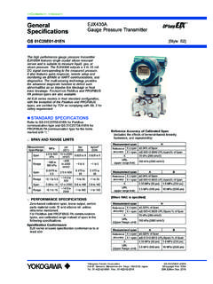
1 User sManual12581191213710634digitalYEWFLO Series Vortex Flowmeter Installation Manual [Style:S2]IM 01F06A01-01EN6th EditionIM 01F06A01-01 ENVortex Flowmeter (Integral Type : DY###) Vortex Flowmeter (Remote Type Detector: DY###-N) Vortex Flow Converter(Remote Type Converter: DYA)This book is a Manual that extract the contents related to the Installation and wiring from the manuals are some differences, but does not affect the safety of the product performance and 01F06A00-01 ENdigitalYEWFLO Series Vortex FlowmeterIM 01F06F00-01 ENdigitalYEWFLO Series Vortex FlowmeterFOUNDATION Fieldbus Communication TypeGS 01F06S00-01 ENdigitalYEWFLO Series Vortex Flowmeter List of RoHS (2011/65/EU) Directive Compliant ProductsIM 01F06A00-01EN-RdigitalYEWFLO Series Vortex Flowmeter Difference to IM 01F06A00-01EN (for European Market, Read and of IM 01F06A00-01EN)1.
2 INTRODUCTION2. HANDLING PRECAUTIONS3. INSTALLATION4. WIRING5. BASIC OPERATING PROCEDURES (DISPLAY)6. PARAMETERS7. COMMUNICATION (BRAIN / HART)8. OPERATION9. ERRORS AND COUNTERMEASURES FOR DISPLAY UNIT AND BRAIN PROTOCOL10. EXPLOSION PROTECTED TYPE INSTRUMENT11. COMMUNICATION (FIELDBUS)12. EXPLOSION PROTECTED TYPE INSTRUMENT FOR FIELDBUS COMMUNICATION TYPE13. PED (PRESSURE EQUIPMENT DIRECTIVE) Installation AND OPERATING PRECAUTIONS FOR FLAMEPROOF ENCLOSURE d CERTIFIED UNDER JAPANESE TYPE CERTIFICATION1IM 01F06A01-01EN <Contents> digitalYEWFLO Series Vortex Flowmeter Installation ManualIM 01F06A01-01EN 6th Edition6th Edition : July 2021 (KP)All Rights Reserved. Copyright 2015, Yokogawa Electric CorporationContents1. Using This Instrument Safely.
3 Warranty ..52. HANDLING PRECAUTIONS .. Checking Model and Specifications .. Transportation and Storage Precautions ..63. Installation .. Installation Precautions .. Piping Precautions .. maintenance of Piping .. Cryogenic and High Process Temperature Version Insulation .. Mounting Procedures .. Changing the Converter and the Terminal Box Orientation .. Indicator Removal and Rotation .. Amplifier Unit Removal .. Amplifier Unit Assembling ..174. WIRING .. Load Resistance of Output Condition .. Selection of Wires .. Connection .. Connection of DYC Remote Type Signal Cable .. End Processing Method of DYC Remote Type Signal Cable .. For Remote Type Vortex Flowmeter (DY-N) .. For DYA Remote Type Converter .. Wiring Procedures and Precautions .. Grounding.
4 265. BASIC OPERATING PROCEDURES (DISPLAY) .. Display Configuration ..276. PARAMETERS .. digitalYEWFLO Parameters .. Parameter Configuration .. Self-Diagnostic (Error Code List) ..297. COMMUNICATION (BRAIN / HART) .. Connection Method for the Connection Method for the HART Configuration Tool ..318. OPERATION .. Adjustment .. Zero Adjustment .. Span Adjustment .. Loop Test .. Totalizer Start and Totalizer Reset .. Setting of Pulse Output (Scaling) .. Setting of Burnout Switch .. Setting of Write Protect Switch .. Power Failure .. Adjustment for Manual Mode .. Low Cut Adjustment .. Zero Tuning ..349. ERRORS AND COUNTERMEASURES FOR DISPLAY UNIT AND BRAIN PROTOCOL .. Large Errors or Unstable Output .. The Indication Goes to Zero at Certain No Output When The Fluid is Flowing.
5 Output is Indicated at Zero Flow .. Multi-Variable Type (/MV) ..3910. EXPLOSION PROTECTED TYPE INSTRUMENT .. ATEX .. FM .. IECEx .. CSA .. TIIS ..5311. COMMUNICATION (FIELDBUS) .. Amplifier for Fieldbus Communication Type .. Connection of Host Setting .. Power-on of digitalYEWFLO and Bus ..562IM 01F06A01-01EN <Contents> Generation of Alarm .. Indication of Alarm .. Alarms and Events .. Simulation Function ..5812. EXPLOSION PROTECTED TYPE INSTRUMENT FOR FIELDBUS COMMUNICATION TYPE .. ATEX .. FM .. IECEx .. CSA .. TIIS ..7113. PED (PRESSURE EQUIPMENT DIRECTIVE) ..72 Installation AND OPERATING PRECAUTIONS FOR FLAMEPROOF ENCLOSURE d CERTIFIED UNDER JAPANESE TYPE CERTIFICATION ..73 Revision Information <1. INTRODUCTION>3IM 01F06A01-01 ENINTRODUCTION11.
6 INTRODUCTIONT hank you for purchasing the digitalYEWFLO Series Vortex Manual provides the basic guidelines for Installation and wiring procedures of integral type Vortex Flowmeter , remote type Vortex flow detector, and remote type Vortex flow converter through the communication does not provide the product specific functional specifications and explanations, maintenance , troubleshooting. For the items which are not covered in this Manual , read the applicable user s manuals on the front page. These manuals can be downloaded from the website of Yokogawa. To ensure correct use of the instrument, read these manuals thoroughly and fully understand how to operate the instrument before operating address: Regarding This Manual This Manual should be provided to the end user. The contents of this Manual may be changed without prior notice.
7 All rights are reserved. No part of this Manual may be reproduced in any form without Yokogawa s written permission. Yokogawa makes no warranty of any kind with regard to this material, including, but not limited to, implied warranties of merchantability and suitability for a particular purpose. All reasonable effort has been made to ensure the accuracy of the contents of this Manual . However, if any errors or omissions are found, please inform Yokogawa. The specifications covered by this Manual are limited to those for the standard type under the specified model number break-down and do not cover custom-made instruments. Please note that this Manual may not be revised for any specification changes, construction changes or operating part changes that are not considered to affect function or performance.
8 Yokogawa assumes no responsibilities for this product except as stated in the warranty. If the customer or any third party is harmed by the use of this product, Yokogawa assumes no responsibility for any such harm owing to any defects in the product which were not predictable, or for any indirect damages. Safety and Modification Precautions The following general safety precautions must be observed during all phases of operation, service, and repair of this instrument. Failure to comply with these precautions or with specific WARNINGS given elsewhere in this Manual violates safety standards of design, manufacture, and intended use of the instrument. Yokogawa assumes no liability for the customer s failure to comply with these requirements. If this instrument is used in a manner not specified in this Manual , the protection provided by this instrument may be impaired.
9 The following safety symbol marks are used in this Manual and A WARNING sign denotes a hazard. It calls attention to procedure, practice, condition or the like, which, if not correctly performed or adhered to, could result in injury or death of CAUTION sign denotes a hazard. It calls attention to procedure, practice, condition or the like, which, if not correctly performed or adhered to, could result in damage to or destruction of the IMPORTANT sign denotes that attention is required to avoid damage to the instrument or system NOTE sign denotes information necessary for essential understanding of operation and features. <1. INTRODUCTION>4IM Using This Instrument Safely(1) InstallationWARNING Installation of the Vortex Flowmeter must be performed by expert engineer or skilled personnel.
10 No operator shall be permitted to perform procedures relating to Installation . The Vortex Flowmeter must be installed within the specification conditions. The Vortex Flowmeter is a heavy instrument. Be careful that no damage is caused to personnel through accidentally dropping it, or by exerting excessive force on the Vortex Flowmeter . When moving the Vortex Flowmeter , always use a trolley and have at least two people carry it. When the Vortex Flowmeter is processing hot fluids, the instrument itself may become extremely hot. Take sufficient care not to get burnt. Where the fluid being processed is a toxic substance, avoid contact with the fluid and avoid inhaling any residual gas, even after the instrument has been taken off the piping line for maintenance and so forth. Do not apply excessive weight, for example, a person stepping on the Vortex Flowmeter .