Transcription of Document name WECC Solar Plant Dynamic Modeling Guidelines
1 Document name WECC Solar Plant Dynamic Modeling Guidelines Category ( ) Regional Reliability Standard ( ) Regional Criteria ( ) Policy (X ) Guideline ( ) Report or other ( ) Charter Document date April 2014 Adopted/approved by TSS Date adopted/approved May 8, 2014 Custodian (entity responsible for maintenance and upkeep) M&VWG Stored/filed Physical location: Web URL: Previous name/number N/A Status (X) in effect ( ) usable, minor formatting/editing required ( ) modification needed ( ) superseded by _____ ( ) other _____ ( ) obsolete/archived) 1 Western Electricity Coordinating Council Modeling and Validation Work Group WECC PV power Plant Dynamic Modeling Guide Prepared by WECC Renewable Energy Modeling Task Force April 2014 2 Contents 1 Introduction.
2 3 2 Background .. 3 3 General Considerations for Dynamic Simulation of PV plants .. 5 Appropriate Models for Bulk System Simulations .. 5 Load Flow Representation .. 5 Implications of Collector System Equivalencing .. 6 Active and Reactive power Control .. 6 Fault Ride-Through and Representation of Protection Limits .. 6 Model parameters .. 7 4 WECC Generic Models .. 7 Technical Specifications for the WECC Generic Models .. 7 WECC Generic Model for Large-scale PV plants .. 8 Model Structure .. 8 Model call .. 9 Scaling for the PV Plant size and reactive capability .. 10 Volt/Var controls options .. 11 Active power control options .. 11 Representation of Voltage and Frequency Protection .. 12 Sample simulation results .. 12 WECC Generic Model for Distributed and Small PV 12 Model Structure.
3 12 Model call .. 13 Scaling for the PV Plant size and reactive capability .. 14 Volt/Var 14 Active power Controls .. 14 Generation tripping .. 15 Sample simulation results .. 15 5 Summary .. 16 Appendix Detailed Model Description .. 17 Renewable Energy Generator/Converter Model (REGC_A) .. 17 Description .. 17 Block Diagram .. 17 Parameters and Default Settings .. 18 Internal Variables and Output Channels .. 18 REEC_B Renewable Energy Electrical Control Model for PV plants .. 19 Description .. 19 Block Diagram .. 19 Parameters and sample settings .. 20 Internal variables and Output Channels .. 20 REPC_A - Renewable Energy Plant Control Model .. 22 Description .. 22 Block Diagram .. 22 Parameters and sample settings .. 23 Internal Variables and Output Channels.
4 24 Document Version Control .. 25 3 1 Introduction Grid-connected photovoltaic (PV) systems cover a wide range of applications. Most PV systems are residential (up to several kW) and commercial scale (up to several MW) connected to distribution networks. However, many PV systems are large generation facilities (some exceeding 100 MW) and are connected to the transmission system. NERC Reliability Standards require that power flow and dynamics models be provided, in accordance with regional requirements and procedures. Under the existing WECC Modeling guidelines1 all PV power plants with aggregated capacity 20 MVA or larger must be modeled explicitly in power flow and dynamics . This means that these plants must not be load-netted or modeled as negative load.
5 Manufacturer-specific Dynamic models commonly provided for interconnection studies are not adequate for regional planning. For this application, WECC requires the use of approved models, that are public (non-proprietary), are available as standard-library models, and have been tested and validated in accordance to WECC Guidelines . Approved models are listed in the WECC Approved Dynamic Model List. This Document is a guide for the application WECC PV power Plant generic Dynamic models recently been adopted by WECC. The user should always refer to module documentation maintained by the simulation software vendor. For additional technical details, the user can reference the WECC-approved model specifications2.
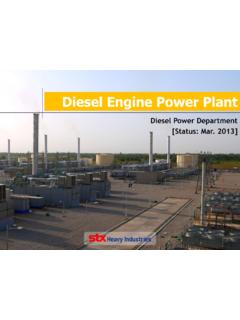
6 Subject to some limitations, and with proper selection of model structure and parameters, the models are suitable for representation of large-scale PV plants and distribution- connected PV aggregated to a transmission bus. Both PV system models require explicit representation of the generation in the power flow model. PV power Plant Modeling will continue to be an area of active research. Models will continue to evolve with changes in technology and interconnection requirements. Also, PV power plants model validation against reference data remains a challenge due to limited industry experience. 2 Background Solar power plants are different than conventional power plants . The interface to the grid is an inverter (see Figure 1) connected to a PV array.
7 Figure 1 A topology commonly found in utility-scale three-phase PV inverters. 1 WECC Data Preparation Procedural Manual for power Flow Base Cases and Dynamic Stability Data , WECC System Review Work Group, Approved March 27, 2013. 2 Model specifications are accessible from the WECC website in this folder. 4 Inverters are characterized by low short circuit current contribution, lack of mechanical inertia, and high-bandwidth (fast) controls. A primary function of the inverter controls is to make the most efficient use of available energy being produced by the PV array, while ensuring that the magnitude of AC current does not exceed the rating of the inverter. PV plants do not have any inherent inertial or frequency response capabilities.
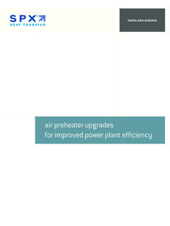
8 Figure 2 shows the topology of a large PV power Plant . Large PV plants typically have several medium voltage radial feeders. The PV inverters are connected to the feeders via step-up transformers, with several inverters sharing one step-up transformer. Some plants designs include capacitors or other reactive support systems that work in conjunction with the inverters to meet reactive power capability and control requirements at the point of interconnection. A Plant controller provides the power factor reference to the inverters3 and Plant -level reactive power support equipment, if present. The Plant controller processes measurements at the point of interconnection and commands issued from the fleet remote operations center or directly from the transmission system operator.
9 Figure 2 Typical PV power Plant Topology Much of the existing PV generation in WECC consists of small PV systems deployed in customer premises, connected directly to distribution service voltage. These systems do not typically have a Plant controller, and the inverter manages the grid interface. Some PV systems as large as 20 MW are connected directly to distribution substations using a dedicated medium voltage feeder. 3 Although not used commonly, the Plant controller could also provide active power to the inverters to prevent the Plant output from exceeding a certain limit. 5 PV plants are considered non-dispatchable because the energy source ( Solar irradiance) is variable.
10 However, reactive power is dispatchable within the capability of the inverters and Plant -level reactive compensation. 3 General Considerations for Dynamic Simulation of PV plants Appropriate Models for Bulk System Simulations The WECC generic models were designed for transmission planning studies that involve a complex network, and a large set of generators, loads and other Dynamic components. The objective is to assess Dynamic performance of the system, particularly recovery dynamics following grid-side disturbances such as transmission-level faults. In this context, WECC uses positive-sequence power flow and Dynamic models that provide a good representation of recovery dynamics using integration time steps of one quarter cycle.