Transcription of DS18S20 High-Precision 1-Wire Digital Thermometer
1 Pin ConfigurationsGeneral DescriptionThe DS18S20 Digital Thermometer provides 9-bit Celsius temperature measurements and has an alarm function with nonvolatile user-programmable upper and lower trig-ger points. The DS18S20 communicates over a 1-Wire bus that by definition requires only one data line (and ground) for communication with a central microprocessor . In addition, the DS18S20 can derive power directly from the data line ( parasite power ), eliminating the need for an external power DS18S20 has a unique 64-bit serial code, which allows multiple DS18S20s to function on the same 1-Wire bus. Thus, it is simple to use one microprocessor to control many DS18S20s distributed over a large area. Applications that can benefit from this feature include HVAC environmental controls, temperature monitoring systems inside buildings, equipment, or machinery, and process monitoring and control Thermostatic Controls Industrial Systems Consumer Products Thermometers Thermally Sensitive SystemsBenefits and Features Unique 1-Wire Interface Requires Only One Port Pin for Communication Maximize System Accuracy in Broad Range of Thermal Management Applications Measures Temperatures from -55 C to +125 C (-67 F to +257 F) C Accuracy from -10 C to +85 C 9-Bit Resolution No External Components Required Parasite Power Mode Requires Only 2 Pins for Operation (DQ and GND)
2 Simplifies Distributed Temperature-Sensing Applications with Multidrop Capability Each Device Has a Unique 64-Bit Serial Code Stored in On-Board ROM Flexible User-Definable Nonvolatile (NV) Alarm Settings with Alarm Search Command Identifies Devices with Temperatures Outside Programmed Limits Available in 8-Pin SO (150 mils) and 3-Pin TO-92 PackagesOrdering Information appears at end of data is a registered trademark of Maxim Integrated Products, ; Rev 3; 4/15 BOTTOM (150 mils)(DS18S20Z) +1437856DS18S20123 GNDDQVDD1 123 TOP VIEWTO-92 ( DS18S20 ) DS18S20 High-Precision 1-Wire Digital Thermometer Voltage Range on Any Pin Relative to Ground .. to + Power Dissipation (TA = +70 C) 8-Pin SO (derate C above +70 C) .. 3-Pin TO-92 (derate C above +70 C) ..500mWOperating Temperature Range ..-55 C to +125 CStorage Temperature Range ..-55 C to +125 CLead Temperature (soldering, 10s).
3 +260 CSoldering Temperature (reflow) Lead(Pb) +260 C Containing lead(Pb) ..+240 CNote 1: All voltages are referenced to ground. Note 2: The Pullup Supply Voltage specification assumes that the pullup device is ideal, and therefore the high level of the pul-lup is equal to VPU. In order to meet the VIH spec of the DS18S20 , the actual supply rail for the strong pullup transistor must include margin for the voltage drop across the transistor when it is turned on; thus: VPU_ACTUAL = VPU_IDEAL + VTRANSISTOR. Note 3: See typical performance curve in Figure 4: Logic-low voltages are specified at a sink current of 5: To guarantee a presence pulse under low voltage parasite power conditions, VILMAX may have to be reduced to as low as Note 6: Logic-high voltages are specified at a source current of 7: Standby current specified up to +70 C.
4 Standby current typically is 3 A at +125 8: To minimize IDDS, DQ should be within the following ranges: GND DQ GND + or VDD DQ 9: Active current refers to supply current during active temperature conversions or EEPROM 10: DQ line is high ( high-Z state).Note 11: Drift data is based on a 1000-hour stress test at +125 C with VDD = (VDD = to , TA = -55 C to +125 C, unless otherwise noted.)PARAMETERSYMBOLCONDITIONSMINTYPMA XUNITSS upply VoltageVDDL ocal Power (Note 1)+ + Supply VoltageVPUP arasite Power(Note 1, 2)+ + Power+ ErrortERR-10 C to +85 C(Note 3) C-55 C to +125 C 2 Input Logic-LowVIL(Note 1, 4, 5) + Logic-HighVIHL ocal Power(Note 1, 6)+ lower of or VDD + Power+ CurrentILVI/O = (Note 1) CurrentIDDS(Note 7, 8)7501000nAActive CurrentIDDVDD = 5V (Note 9) Input CurrentIDQ(Note 10)5 ADrift(Note 11) CDS18S20 High-Precision 1-Wire Digital Thermometer Integrated 2 Absolute Maximum RatingsThese are stress ratings only and functional operation of the device at these or any other conditions above those indicated in the operation sections of this specification is not implied.
5 Exposure to absolute maximum rating conditions for extended periods of time may affect Electrical Characteristics(VDD = to , TA = -55 C to +100 C, unless otherwise noted.)(VDD = to ; TA = -55 C to +125 C, unless otherwise noted.)Note 12: See the timing diagrams in Figure 13: Under parasite power, if tRSTL > 960 s, a power-on reset may Write Cycle TimetWR210msEEPROM WritesNEEWR-55 C to +55 C50kwritesEEPROM Data RetentiontEEDR-55 C to +55 C10yearsPARAMETERSYMBOLCONDITIONSMINTYPM AXUNITST emperature Conversion TimetCONV(Note 12)750msTime to Strong Pullup OntSPONS tart Convert T Command Issued10 sTime SlottSLOT(Note 12)60120 sRecovery TimetREC(Note 12)1 sWrite 0 Low TimetLOW0(Note 12)60120 sWrite 1 Low TimetLOW1(Note 12)115 sRead Data ValidtRDV(Note 12)15 sReset Time HightRSTH(Note 12)480 sReset Time LowtRSTL(Note 12, 13)480 sPresence-Detect HightPDHIGH(Note 12)1560 sPresence-Detect LowtPDLOW(Note 12)60240 sCapacitanceCIN/OUT25pFFigure 1.
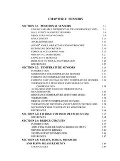
6 Typical Performance Curve DS18S20 TYPICAL ERROR ERROR ( C)070102030405060 TEMPERATURE ( C)+3s ERRORMEAN ERROR-3s ERRORDS18S20 High-Precision 1-Wire Digital Thermometer Integrated 3AC Electrical Characteristics NV MemoryAC Electrical CharacteristicsPINNAMEFUNCTIONTO-92SO15 GNDG round24 DQData Input/Output. Open-drain 1-Wire interface pin. Also provides power to the device when used in parasite power mode (see the Powering the DS18S20 section.)33 VDDO ptional VDD. VDD must be grounded for operation in parasite power mode. 1, 2, 6, 7, ConnectionFigure 2. Timing DiagramsSTART OF NEXT CYCLE1-Wire WRITE ZERO TIME SLOTtRECtSLOTtLOW01-Wire READ ZERO TIME SLOTtRECtSLOTSTART OF NEXT CYCLEtRDV1-Wire RESET PULSE1-Wire PRESENCE DETECTtRSTLtRSTHtPDHIGHPRESENCE DETECTtPDLOWRESET PULSE FROM HOSTDS18S20 High-Precision 1-Wire Digital Thermometer Integrated 4 Pin DescriptionOverviewFigure 3 shows a block diagram of the DS18S20 , and pin descriptions are given in the Pin Description table.
7 The 64-bit ROM stores the device s unique serial code. The scratchpad memory contains the 2-byte temperature register that stores the Digital output from the temperature sensor. In addition, the scratchpad provides access to the 1-byte upper and lower alarm trigger registers (TH and TL). The TH and TL registers are nonvolatile (EEPROM), so they will retain data when the device is powered DS18S20 uses Maxim s exclusive 1-Wire bus proto-col that implements bus communication using one control signal. The control line requires a weak pullup resistor since all devices are linked to the bus via a 3-state or open-drain port (the DQ pin in the case of the DS18S20 ). In this bus system, the microprocessor (the master device) identifies and addresses devices on the bus using each device s unique 64-bit code.
8 Because each device has a unique code, the number of devices that can be addressed on one bus is virtually unlimited. The 1-Wire bus protocol, including detailed explanations of the commands and time slots, is covered in the 1-Wire Bus System feature of the DS18S20 is the ability to operate without an external power supply. Power is instead sup-plied through the 1-Wire pullup resistor via the DQ pin when the bus is high. The high bus signal also charges an internal capacitor (CPP), which then supplies power to the device when the bus is low. This method of deriving power from the 1-Wire bus is referred to as parasite power. As an alternative, the DS18S20 may also be powered by an external supply on Measuring TemperatureThe core functionality of the DS18S20 is its direct-to-dig-ital temperature sensor.
9 The temperature sensor output has 9-bit resolution, which corresponds to C steps. The DS18S20 powers-up in a low-power idle state; to initiate a temperature measurement and A-to-D conver-sion, the master must issue a Convert T [44h] command. Following the conversion, the resulting thermal data is stored in the 2-byte temperature register in the scratch-pad memory and the DS18S20 returns to its idle state. If the DS18S20 is powered by an external supply, the master can issue read-time slots (see the 1-Wire Bus System section) after the Convert T command and the DS18S20 will respond by transmitting 0 while the tem-perature conversion is in progress and 1 when the con-version is done. If the DS18S20 is powered with parasite power, this notification technique cannot be used since the bus must be pulled high by a strong pullup during the entire temperature conversion.
10 The bus requirements for parasite power are explained in detail in the Powering The DS18S20 3. DS18S20 Block DiagramVPU64-BIT ROMAND1-Wire PORTDQVDDINTERNAL VDDCPPPARASITE POWER CIRCUITMEMORYCONTROL LOGICSCRATCHPAD 8-BIT CRCGENERATORTEMPERATURESENSORALARM HIGH TRIGGER (TH)REGISTER (EEPROM)ALARM LOW TRIGGER (TL)REGISTER (EEPROM) POWER-SUPPLY SENSEDS18S20 High-Precision 1-Wire Digital Thermometer Integrated 5 The DS18S20 output data is calibrated in degrees cen-tigrade; for Fahrenheit applications, a lookup table or conversion routine must be used. The temperature data is stored as a 16-bit sign-extended two s complement num-ber in the temperature register (see Figure 4). The sign bits (S) indicate if the temperature is positive or negative: for positive numbers S = 0 and for negative numbers S = 1. Table 1 gives examples of Digital output data and the corresponding temperature greater than 9 bits can be calculated using the data from the temperature, COUNT REMAIN and COUNT PER C registers in the scratchpad.