Transcription of DS28E05 1-Wire EEPROM - Maxim Integrated
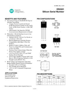
1 DS28E051-Wire EEPROM General DescriptionThe DS28E05 is a 112-byte user-programmable EEPROM organized as 7 pages of 16 bytes each. memory pages can be individually set to write protected or EPROM emulation mode through protection byte settings. Each part has its own guaranteed unique 64-bit ROM identi-fication number (ROM ID) that is factory programmed into the chip. The DS28E05 communicates over Maxim Integrated s single contact 1-Wire interface at overdrive speed with the ROM ID acting as node address in the case of a multiple-device 1-Wire Accessory/PCB Identification Medical Sensor Calibration Data Storage Analog Sensor Calibration Aftermarket Management of ConsumablesFeatures Single-Contact 1-Wire Interface 112 Bytes User EEPROM with 1K Write Cycles Programmable Write Protection and OTP EPROM Emulation Modes for User memory Unique Factory-Programmed 64-Bit ROM ID Number Communicates with Host at Up to (Overdrive Only) Operating Range.
2 To , -40 C to +85 C 8kV HBM ESD Protection (typ) on IO Pin 4-Ball UCSP, 2-Pad SFN, 3-Pin SOT23 and 6-Pin TSOC Packages19-6568; Rev 3; 2/17 Ordering Information appears at end of data Application Circuit1-Wire is a registered trademark of Maxim Integrated Products, Inc. CPIOXPIOY100k DS28E05 RPUPVCCQ1IO*NOTE: OPTIONAL Q1 LOW-IMPEDANCE BYPASS OR EQUALLY DRIVE LOGIC 1 WITH PIOYBIDIRECTIONALGNDVCCGNDOPEN DRAIN PORT1k *PMV65 XPDS28E051-Wire Integrated 2 Electrical Characteristics(TA = -40 C to +85 C, unless otherwise noted.) (Note 1)IO Voltage Range to GND .. to Sink 20mAOperating Temperature Range ..-40 C to +85 CJunction Temperature ..+150 CStorage Temperature Range ..-55 C to +125 CLead Temperature (soldering, 10s) ..+300 CSoldering Temperature (reflow).
3 +260 CStresses beyond those listed under Absolute Maximum Ratings may cause permanent damage to the device. These are stress ratings only, and functional operation of the device at these or any other conditions beyond those indicated in the operational sections of the specifications is not implied. Exposure to absolute maximum rating conditions for extended periods may affect device Maximum RatingsPARAMETERSYMBOLCONDITIONSMINTYPMA XUNITSIO PIN: GENERAL DATA1-Wire Pullup VoltageVPUP(Note 2) Pullup Resistance RPUPVPUP = to (Note 3)3001500 VPUP = to (Note 3)300750 Input CapacitanceCIO(Notes 4, 5)1500pFInput Load Current ILIO pin at VPUP520 AIO pin at VPUP = +5%28 High-to-Low Switching ThresholdVTL(Notes 6, 7) x VPUPVI nput Low Voltage VILVPUP = to (Notes 2, 8) = to (Notes 2, 8) Switching ThresholdVTH(Notes 6, 9) x VPUPVS witching HysteresisVHYVPUP = to (Notes 6, 10) = to (Notes 6, 10) Low VoltageVOLVPUP = to , IOL = 4mA (Note 11) = to , IOL = 2mA (Note 11) Time tREC(Notes 2, 12)5 sTime Slot Duration tSLOT(Notes 2, 13)13 sIO PIN.
4 1-Wire RESET, PRESENCE DETECT CYCLER eset Low Time tRSTL(Note 2)4880 sReset High Time tRSTH(Note 14)48 sPresence Detect Sample Time tMSP(Notes 2, 15)810 sIO PIN: 1-Wire WRITEW rite-Zero Low Time tW0L(Notes 2, 16)816 sWrite-One Low Time tW1L(Notes 2, 16) sIO PIN: 1-Wire READRead Low Time tRL(Notes 2, 17) - sRead Sample Time tMSR(Notes 2, 17)tRL + 2 sDS28E051-Wire Integrated 3 Electrical Characteristics (continued)(TA = -40 C to +85 C, unless otherwise noted.) (Note 1)Note 1: Limits are 100% production tested at TA = +25 C and/or TA = +85 C. Limits over the operating temperature range and rel-evant supply voltage range are guaranteed by design and characterization. Typical values are not 2: System 3: Maximum allowable pullup resistance is a function of the number of 1-Wire devices in the system and 1-Wire recovery times.
5 The specified value here applies to systems with only one device and with the minimum 1-Wire recovery 4: Typical value represents the internal parasite capacitance when VPUP is first applied. Once the parasite capacitance is charged, it does not affect normal 5: Guaranteed by design and/or characterization only. Not production 6: VTL, VTH, and VHY are a function of the internal supply voltage, which is a function of VPUP, RPUP, 1-Wire timing, and capacitive loading on IO. Lower VPUP, higher RPUP, shorter tREC, and heavier capacitive loading all lead to lower values of VTL, VTH, and 7: Voltage below which, during a falling edge on IO, a logic 0 is 8: The voltage on IO must be less than or equal to VILMAX at all times the master is driving IO to a logic 0 9: Voltage above which, during a rising edge on IO, a logic 1 is 10: After VTH is crossed during a rising edge on IO, the voltage on IO must drop by at least VHY to be detected as logic 11: The I-V characteristic is linear for voltages less than 12: Applies to a single device attached to a 1-Wire 13: Defines maximum possible bit rate.
6 Equal to 1/(tW0 LMIN + tRECMIN).Note 14: An additional reset or communication sequence cannot begin until the reset high time has 15: Interval after tRSTL during which a bus master can read a logic 0 on IO if there is a DS28E05 present. The power-up pres-ence detect pulse could be outside this interval but will be complete within 2ms for a VPUP or 20ms for a VPUP after 16: in Figure 10 represents the time required for the pullup circuitry to pull the voltage on IO up from VIL to VTH. The actual maximum duration for the master to pull the line low is tW1 LMAX + tF - and tW0 LMAX + tF - , 17: in Figure 10 represents the time required for the pullup circuitry to pull the voltage on IO up from VIL to the input-high threshold of the bus master.
7 The actual maximum duration for the master to pull the line low is tRLMAX + 18: Current drawn from IO during the EEPROM programming interval, during which the voltage at IO must not drop below 19: The tPROG interval begins immediately after the trailing rising edge on IO for the last time slot of the Release byte for a valid Write memory sequence. Interval ends once the device s self-timed EEPROM programming cycle is complete and the current drawn by the device has returned from IPROG to 20: Write-cycle endurance is tested in compliance with 21: Not 100% production tested; guaranteed by reliability monitor 22: Data retention is tested in compliance with 23: Guaranteed by 100% production test at elevated temperature for a shorter time; equivalence of this production test to the data sheet limit at operating temperature range is established by reliability 24: EEPROM writes can become nonfunctional after the data-retention time is exceeded.
8 Long-term storage at elevated tem-peratures is not Current IPROG(Notes 5, 18)400 AProgramming Time for a 16-BitSegmenttPROG(Note 19)16msWrite/Erase Cycling Endurance NCYTA = +85 C (Notes 20, 21)1000 Data Retention tDRTA = +85 C (Notes 22, 23, 24)10 YearsDS28E051-Wire Integrated 4 Pin DescriptionsPin ConfigurationsDetailed DescriptionThe DS28E05 combines 896 bits of user EEPROM orga-nized as seven 128-bit pages, 64 bits of administrative data memory , and a 64-bit ROM ID in a single chip. Data is transferred serially through the 1-Wire protocol, which requires only a single data lead and a ground user memory can have unrestricted write access (fac-tory default), or can be write protected or put in EPROM emulation mode. Write protection prevents changes to the memory data.
9 EPROM emulation mode logically ANDs memory data with incoming new data, which allows changing bits from 1 to 0, but not vice versa. By chang-ing one bit at a time this mode could be used to create nonvolatile nonresettable counters. For more details refer to Application Note 5042: Implementing Nonvolatile, Nonresettable Counters for Embedded device s 64-bit ROM ID can be used to electronically identify the equipment in which the DS28E05 is used. The ROM ID guarantees unique identification and is also used to address the device in a multidrop 1-Wire network environment, where multiple devices reside on a com-mon 1-Wire bus and operate independently of each other. Applications include accessory/PCB identification, medi-cal sensor calibration data storage, analog sensor calibra-tion, and after-market management of block diagram in Figure 1 shows the relationships between the major control and memory sections of the DS28E05 .
10 The DS28E05 has three main data compo-nents: seven 128-bit pages of user EEPROM , 64 bits of administrative data memory , and a 64-bit ROM ID. Figure 2 shows the hierarchic structure of the 1-Wire protocol. The bus master must first provide one of the five ROM function commands: Read ROM, Match ROM, Search ROM, Skip ROM, or Resume Communication. The protocol required for these ROM function commands is described in Figure 8. After a ROM function command is successfully executed, the memory functions become accessible and the master can select one of the two memory function commands. The function protocols are described in Figure 6. All data is read and written least significant bit ROM IDEach DS28E05 contains a unique ROM ID that is 64 bits long.