Transcription of Ducting Kit Installation Instruction for Hybrid Electric ...
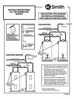
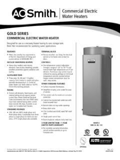
1 Ducting Kit Installation Instruction for Hybrid Electric Heat Pump Water Heaters Introduction:Heat is absorbed from air entering the inlet (left) side of the compressor unit on top of the water heater and transferred to the water inside the storage tank. Cooler dehumidified air exiting the outlet (right) side of the compressor unit is a normal byproduct of operation. In standard installations (using ambient air) a minimum installed space of 750 cubic feet is required as a source of heat. Duct adaptors can be used to redirect inlet and/or outlet air from or to other locations to permit Installation in confined spaces, improve performance and maintain comfort in occupied areas of the the Instruction manual that is shipped with the water heater for further instructions on using Ducting kits for Installation in confined spaces of less than 750 cubic Limitations:There are two duct adaptors; one connects to the inlet side of the top shroud and one to the outlet side.
2 The two cannot be interchanged. Ensure the correct adaptor(s) is ordered prior to Installation . Installation of the duct adaptors requires field supplied 8-inch flexible duct that can be obtained from a local HVAC supply store or home center. Use of smaller diameter Ducting is not can be drawn from or expelled to the outdoors, an attic space, or to another room inside the home. *The maximum length of flexible duct allowed is 10 feet. ** Ducting can be connected to the inlet, outlet or both the inlet and outlet (requires both duct adaptors), though the total length of duct must not exceed 10 feet. For example: when redirecting inlet and outlet air, a maximum of 5 feet of inlet duct and 5 feet of outlet duct is allowed. Variations such as 3/7 feet, 7/3 feet are also permitted, as long as the total duct length does not exceed 10 Considerations:The compressor unit on the water heater is disabled when the temperature of the air flowing to the inlet is lower than 45 F ( C) or higher than 109 F ( C).
3 Air expelled from the outlet will be 7 F (4 C) to 9 F (5 C) cooler than the inlet air. These operational parameters must be considered when deter-mining if a location to duct air from/to will be NOTE:If the compressor unit is disabled for long periods of time due to inlet air temperature being too hot or too cold, the potential energy savings a heat pump water heater is able to provide may be significantly Page 1 Air Inlet: Outdoor air temperatures will often be lower than 45 F ( C) in many regions during fall and winter months. Attic temperature will often exceed 109 F ( C) in many regions during spring and summer months. For units installed in conditioned spaces - Ducting outdoor air to the air inlet of the unit may place additional load on space heating and cooling equipment unless the air outlet is also ducted to an alternate location. Air being drawn from an alternate location inside the home may cause a negative pressure condition inside that area.
4 As a result, cold or hot air from outdoors may be drawn into the structure and place additional load on the space heat-ing and cooling Outlet: The air outlet from a unit installed in a garage or any area where solvents or other chemicals that emit potentially harmful fumes are stored or automobiles are located must never be ducted to any other space inside the building structure. This would include all occupied and unoccupied spaces such as attics or basements. Potentially harmful fumes and vapors from solvents and cleaners or automo-bile exhaust gases could be introduced into living spaces. Cold air blowing from the outlet into an alternate location inside the home may cause cooling discomfort and be objectionable. Cold air blowing from the outlet into an alternate location inside the home may place additional load on space heat-ing equipment during fall and winter months. Ducting outlet air only to an alternate location may cause a negative air pressure in the installed space.
5 As a result cold or hot air from outdoors may be drawn into the structure and place additional load on the space heating and cooling contains: (1) Assembled Inlet Duct Adaptor 323498-000 or (1) Assembled Outlet Duct Adaptor 323497-000 Tools required: #2 Phillips screwdriver, wire cutters, needed: 8 insulated flex duct, duct clamp or strap, appropriate duct termination and duct tapeImportant: Use only factory authorized replacement parts. If you lack the necessary skills to properly perform the instal-lation, you should not proceed, but get help from a qualified service to installing the Duct Adaptor1. Press the power button on the User Interface Module (UIM) to place the water heater in Standby Mode (Figure 1).Note: Power to the board is still present at this Remove all power to the unit at the breaker/fuse panel prior to removing any of the Duct Adaptor:1. If installing the Inlet Duct Adaptor remove the screws from the left louvered access panel of the unit.
6 If installing the Outlet Duct Adaptor remove the screws from the right lou-vered access panel (Figure 2).NOTE: These Adaptors are not interchangeable. 2. Using the eight (8) screws removed earlier attach the new Duct Adaptor panel to the top shroud of the unit. The new Duct Adaptor panel should be oriented with the louvered portion of the panel located at the bottom of the panel to ensure that the panel lines up with the existing holes (Fig-ure 3) Installation of the Ductwork:1. After the desired length of duct has been determined (maxi-mum 10 feet*), carefully cut completely around and through the duct insulation with a pair of scissors. 2. Using a pair of wire cutters, cut the wire inside the core duct. Fold the insulation jacket back away from the core duct (Figure 4).3. Slide at least 1 of the core duct over the Ducting adaptor lip and seal with at least two (2) wraps of duct tape. Addition-ally, secure the core duct with a band clamp or duct strap placed over the Ducting adaptor and tape (Figure 5).
7 4. Slide insulation back over the duct core and the lip of the inlet duct adaptor. Use duct tape to secure the insulation to the inlet duct assembly (Figure 6).5. Add support to the duct work as necessary or as required by local codes. Special attention must be given to prevent large droops in the duct work which could allow moisture to The appropriate duct termination shall be added to the termination end of the duct. This termination shall prevent any debris or rodents from entering the duct work and shall minimally restrict the airflow through the Ducting . In addi-tion the termination shall be designed to prevent rain from entering into the duct work if terminated to the Operation:1. Restore power to the water heater at the breaker/fuse panel. Press the power button on the UIM (Figure 1).2. Follow the Operating Your Water Heater section found in the Installation instructions and Use and Care Guide for restarting your heat pump water Check the UIM for any errors and correct 2 Figure 2 LeftInlet PanelTop Shroud Screws (8) User Interface Module (UIM)Screws (8) Right Outlet PanelAir Flow F/ CLOCKHEAT PUMPELEMENTEFFICIENCYFVACATIONELECTRICHY BRIDEFFICIENCYP ower Button: On - Green Standby - RedFigure 1 User Interface ModuleFigure 3 Figure 5 Duct CoreClampDuct TapeDucting AdaptorDuct InsulationDuct TapeFigure 6 Figure 4 Core DuctDuct InsulationWire CuttersPage 3