Transcription of Electric Power Steering Design Guide With …
1 1 SLVA830 October2016 SubmitDocumentationFeedbackCopyright 2016,TexasInstrumentsIncorporatedElectri cPowerSteeringDesignGuideWithDRV3205-Q1 All trademarksare the propertyof October2016 ElectricPowerSteeringDesignGuideWithDRV3 205-Q1 ABSTRACTThis documentintroducesthe DRV3205-Q1motor-driversolutionand describeshow to designthis deviceinto an electricpower-steeringsystemusingthe advantageof all the diagnosisand (EPS).. Designan an ProtectionFeaturesin ProtectionFeaturesof of VGSS howingthe Operationof the GateDriverat Low ShowingSlewRate(VDS)
2 ControlThroughSPI to OptimizeEMI and an an Someof the FET ProtectionModulesin the CurrentWaveformsin SteadyStatefor Nominal,High,and Low of Tables1 Implementationof ProtectionFeaturesof DRV3205-Q1to DetectHazardsin October2016 SubmitDocumentationFeedbackCopyright 2016,TexasInstrumentsIncorporatedElectri cPowerSteeringDesignGuideWithDRV3205-Q11 IntroductionThe automotivemarketis everevolvingand alwayslookingfor moreprotectionsand diagnosticswithreliableand space-savingsolutionsin safety-criticalmarketniches,suchas electricpowersteering(EPS)and electronicbrakingsystems(EBS).
3 Electricpowersteeringand powertrainmarketsanalysesrevealtheneedfo r new motordriverconceptswith addedfunctionalities,suchas enhancedfault diagnosisandprotectionfeaturesthat requireconstantmonitoringof the 'DRV3000productfamilyis a familyof brushedand brushlessDC motordriversthat haveuniqueperformancerequirements,and that weredesignedand developedspecificallyfor supportingthe protectioncapabilitiesare standardfeaturesof the DRV3000family,suchas supplyovervoltagedetection,motorcurrent- senseamplifiers,and motorovercurrentdetectionthat can be fulfilledunderthe spaceconstrainingand harshconditionsthat the automotiveenvironmentproduces.
4 High temperature,low-voltagestart-stop,and designguideintroducesthe DRV3205-Q1motordriversolutionand explainshow to designthedeviceinto an EPSsystemto take advantageof all the diagnosisand guideis notpart of the EnhancedProtection,Diagnostics,andMonito ring(SLVSCV1)for a moredetailedexplanationof the functionalitiesand specificationsof help customersachievefunctionalsafetygoals,go to contacta localTIrepresentativefor safetymanualsand (EPS)This sectiondescribesone of the mostcommonlyusedautomotive-criticalmotor applications,electricpowersteering(EPS)
5 ,and describeshow to buildan EPSsystemusingthe electricmotorto assiststeeringa vehiclewhenthe driverturnsthesteeringwheelwhichis a replacementof the traditionalmechanicaland benefitsofan EPSsystemare less CO2emissions,higherfuel efficiency,quickeroperation,and maincomponentsof an EPSsystemare the steeringcolumn,an electronicallycontrolledsteeringmotor,an d an inputsof the systemare providedby thedriverat the responsiblefor detectingthe movement(direction,speed,and angle)of the steeringwheeland for sendingthis datato a datais processedand a signalis sent to the motordriverto assistthe driverwith steeringthe be drivenby the DRV3205-Q1devicewhichgeneratesthe current-assisttorquein the EPSsystemthat couldlead to severepotentialeffectsare loss of definedas follows.
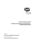
6 Lossof torquecontrol Duringthis failure,the EPSsystemis unableto assistin steeringthe vehiclepossiblybecauseof a shortor an opencircuitin the motorcoil, a damagedmotordriver,or failuresin the Duringthis failure,eitherthe EPSsystemsteerswithoutinputfromthedriver or the assistedtorqueis significantlydeviatedfromdriver s failurecan becausedby a browned-outMCU,failuresin the digitallogic,and failurescan haveunwantedconsequencesbecauseof the very shortreactiontime that thedriverneedsto respondto the ,becausethe driveris constantlyusingthe steeringwheelduringdriving,the driveris exposedto the possibilityof thesefailuresoccurringat any this, the EPSdesignrequirescomponentswhichfeatures ophisticatedprotection,monitoring,and MonitorDriver ProtectionFET ProtectionDRV3205-Q1 SafeTITMM otor Driver BISTPMICM onitorMCU WatchdogSecure CommunicationClockMonitor+-+ (EPS)
7 3 SLVA830 October2016 SubmitDocumentationFeedbackCopyright 2016,TexasInstrumentsIncorporatedElectri cPowerSteeringDesignGuideWithDRV3205-Q1 The electricalpartsof the EPSsystemsthat requirea high levelof monitoringand diagnosticsare: Electroniccontrolunit that controlsthe EPSsystem Motorthat generatesassistedtorque Currentsensorsthat monitorthe motorphasecurrent Powersupplyand batterythat supplyall componentsof the EPSsystem Communicationinterfacebetweenthe EPSsystemand othercontrolunits Sensorsthat readthe inputsignals(torqueand angle)
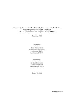
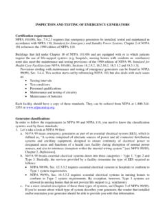
8 And providethemto electricalpart of an EPSsystemconsistsof a mainmicrocontroller,powersupply,motordri ver,andpowertransistorsfor operatingthe ,CANor Flexraycommunicationis usedto interfacewith the controlunitsin the speedare typicallycontrolledwith an controlledthroughvoltageor currentfeedbackfromthe powerstageof the commonarchitecturein an EPSsystemincludesa gatedriverwith integrateddiagnosticsandmonitoringas shownin Figure1. In this case,the DRV3205-Q1devicedirectlyprovidesmuchof thesafetyrelatedtasksin the system,and can help protectagainstfailuresin the MCUand deviceincludesindividualsupplymonitorsfo r eachof the voltagerails (I/O and analogreferencesupplies).
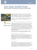
9 The devicealso monitorsthe healthof the MCUusingan MCUis oftenprogrammedwith securecommunicationlinksand driverdiagnosticsoftwareto help ensurethatthe systemis checkedon detectionis includedin the systemsby injectingfaultsinternallyby the gatedriveris the final blockbeforethe powerFETs,this architectureprovidesa localizedshutdownintegratedwith the monitoringand SystemArchitectureMRPSSTPS65381 MCUTMS5703-Phase Pre-DriverDRV3205 Monitoring SchemeHowto Designan October2016 SubmitDocumentationFeedbackCopyright 2016,TexasInstrumentsIncorporatedElectri cPowerSteeringDesignGuideWithDRV3205-Q1T o increaseredundancyin this type of architecture,the DRV3205-Q1devicehas severalcompaniondeviceswhichincludesimil arsets of monitoringand example.
10 TexasInstrument'sTPS65381A-Q1multi-railp owersupplyand TMS570seriesMCUcan be usedto monitoreachotherandthemselvesas shownin Figure1. In this fashion,eachdeviceservesto monitorand protectthe redundancyeliminatesthe needfor additionalon-boardmonitorsand cansimplifythe RedundantMonitoringScheme3 Howto Designan DRV3205-Q1 This sectionis a briefoverviewof TI s additionalinformation,refertoDRV3205-Q1 Three-PhaseAutomotiveGateDriverWithThree IntegratedCurrentShuntAmplifiersand EnhancedProtection,Diagnostics,and Monitoring(SLVSCV1).