Transcription of Electric Power Steering Design Guide With DRV3205 …
1 1 SLVA830 October2016 SubmitDocumentationFeedbackCopyright 2016,TexasInstrumentsIncorporatedElectri cPowerSteeringDesignGuideWithDRV3205-Q1 All trademarksare the propertyof October2016 ElectricPowerSteeringDesignGuideWithDRV3 205-Q1 ABSTRACTThis documentintroducesthe DRV3205 -Q1motor-driversolutionand describeshow to designthis deviceinto an electricpower-steeringsystemusingthe advantageof all the diagnosisand (EPS).. Designan an ProtectionFeaturesin ProtectionFeaturesof of VGSS howingthe Operationof the GateDriverat Low ShowingSlewRate(VDS)ControlThroughSPI to OptimizeEMI and an an Someof the FET ProtectionModulesin the CurrentWaveformsin SteadyStatefor Nominal,High,and Low of Tables1 Implementationof ProtectionFeaturesof DRV3205 -Q1to DetectHazardsin October2016 SubmitDocumentationFeedbackCopyright 2016,TexasInstrumentsIncorporatedElectri cPowerSteeringDesignGuideWithDRV3205-Q11 IntroductionThe automotivemarketis everevolvingand alwayslookingfor moreprotectionsand diagnosticswithreliableand space-savingsolutionsin safety-criticalmarketniches,suchas electricpowersteering(EPS)and electronicbrakingsystems(EBS).
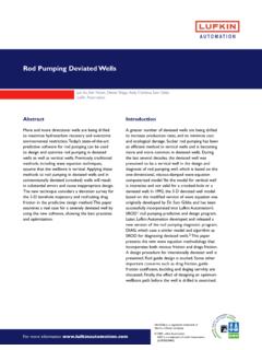
2 Electricpowersteeringand powertrainmarketsanalysesrevealtheneedfo r new motordriverconceptswith addedfunctionalities,suchas enhancedfault diagnosisandprotectionfeaturesthat requireconstantmonitoringof the 'DRV3000productfamilyis a familyof brushedand brushlessDC motordriversthat haveuniqueperformancerequirements,and that weredesignedand developedspecificallyfor supportingthe protectioncapabilitiesare standardfeaturesof the DRV3000family,suchas supplyovervoltagedetection,motorcurrent- senseamplifiers,and motorovercurrentdetectionthat can be fulfilledunderthe spaceconstrainingand harshconditionsthat the automotiveenvironmentproduces:high temperature,low-voltagestart-stop,and designguideintroducesthe DRV3205 -Q1motordriversolutionand explainshow to designthedeviceinto an EPSsystemto take advantageof all the diagnosisand guideis notpart of the EnhancedProtection,Diagnostics,andMonito ring(SLVSCV1)for a moredetailedexplanationof the functionalitiesand specificationsof help customersachievefunctionalsafetygoals,go to contacta localTIrepresentativefor safetymanualsand (EPS)This sectiondescribesone of the mostcommonlyusedautomotive-criticalmotor applications,electricpowersteering(EPS)
3 ,and describeshow to buildan EPSsystemusingthe electricmotorto assiststeeringa vehiclewhenthe driverturnsthesteeringwheelwhichis a replacementof the traditionalmechanicaland benefitsofan EPSsystemare less CO2emissions,higherfuel efficiency,quickeroperation,and maincomponentsof an EPSsystemare the steeringcolumn,an electronicallycontrolledsteeringmotor,an d an inputsof the systemare providedby thedriverat the responsiblefor detectingthe movement(direction,speed,and angle)of the steeringwheeland for sendingthis datato a datais processedand a signalis sent to the motordriverto assistthe driverwith steeringthe be drivenby the DRV3205 -Q1devicewhichgeneratesthe current-assisttorquein the EPSsystemthat couldlead to severepotentialeffectsare loss of definedas follows.
4 Lossof torquecontrol Duringthis failure,the EPSsystemis unableto assistin steeringthe vehiclepossiblybecauseof a shortor an opencircuitin the motorcoil, a damagedmotordriver,or failuresin the Duringthis failure,eitherthe EPSsystemsteerswithoutinputfromthedriver or the assistedtorqueis significantlydeviatedfromdriver s failurecan becausedby a browned-outMCU,failuresin the digitallogic,and failurescan haveunwantedconsequencesbecauseof the very shortreactiontime that thedriverneedsto respondto the ,becausethe driveris constantlyusingthe steeringwheelduringdriving,the driveris exposedto the possibilityof thesefailuresoccurringat any this, the EPSdesignrequirescomponentswhichfeatures ophisticatedprotection,monitoring,and MonitorDriver ProtectionFET ProtectionDRV3205-Q1 SafeTITMM otor Driver BISTPMICM onitorMCU WatchdogSecure CommunicationClockMonitor+-+ (EPS)3 SLVA830 October2016 SubmitDocumentationFeedbackCopyright 2016,TexasInstrumentsIncorporatedElectri cPowerSteeringDesignGuideWithDRV3205-Q1 The electricalpartsof the EPSsystemsthat requirea high levelof monitoringand diagnosticsare.
5 Electroniccontrolunit that controlsthe EPSsystem Motorthat generatesassistedtorque Currentsensorsthat monitorthe motorphasecurrent Powersupplyand batterythat supplyall componentsof the EPSsystem Communicationinterfacebetweenthe EPSsystemand othercontrolunits Sensorsthat readthe inputsignals(torqueand angle)and providethemto electricalpart of an EPSsystemconsistsof a mainmicrocontroller,powersupply,motordri ver,andpowertransistorsfor operatingthe ,CANor Flexraycommunicationis usedto interfacewith the controlunitsin the speedare typicallycontrolledwith an controlledthroughvoltageor currentfeedbackfromthe powerstageof the commonarchitecturein an EPSsystemincludesa gatedriverwith integrateddiagnosticsandmonitoringas shownin Figure1.
6 In this case,the DRV3205 -Q1devicedirectlyprovidesmuchof thesafetyrelatedtasksin the system,and can help protectagainstfailuresin the MCUand deviceincludesindividualsupplymonitorsfo r eachof the voltagerails (I/O and analogreferencesupplies).The devicealso monitorsthe healthof the MCUusingan MCUis oftenprogrammedwith securecommunicationlinksand driverdiagnosticsoftwareto help ensurethatthe systemis checkedon detectionis includedin the systemsby injectingfaultsinternallyby the gatedriveris the final blockbeforethe powerFETs,this architectureprovidesa localizedshutdownintegratedwith the monitoringand SystemArchitectureMRPSSTPS65381 MCUTMS5703-Phase Pre-DriverDRV3205 Monitoring SchemeHowto Designan October2016 SubmitDocumentationFeedbackCopyright 2016,TexasInstrumentsIncorporatedElectri cPowerSteeringDesignGuideWithDRV3205-Q1T o increaseredundancyin this type of architecture.
7 The DRV3205 -Q1devicehas severalcompaniondeviceswhichincludesimil arsets of monitoringand example,TexasInstrument'sTPS65381A-Q1mul ti-railpowersupplyand TMS570seriesMCUcan be usedto monitoreachotherandthemselvesas shownin Figure1. In this fashion,eachdeviceservesto monitorand protectthe redundancyeliminatesthe needfor additionalon-boardmonitorsand cansimplifythe RedundantMonitoringScheme3 Howto Designan DRV3205 -Q1 This sectionis a briefoverviewof TI s additionalinformation,refertoDRV3205-Q1 Three-PhaseAutomotiveGateDriverWithThree IntegratedCurrentShuntAmplifiersand EnhancedProtection,Diagnostics,and Monitoring(SLVSCV1).The DRV3205 -Q1deviceis a 45-Vautomotivegate-driverdevicefor devicereducesthe externalcomponentcountin the systemby integratingthreehigh-accuracyand temperature-compensatedhalf-bridgedriver s,a boostconverter,threebidirectionalcurrent -shuntamplifiers,and severaltypesof protectionand DRV3205 -Q1deviceprovidesapplication-leve lprotectionincludingovercurrent,shoot-th rough,and devicealso includesmonitoringcircuitsfor the internalclock,undervoltageand overvoltageof thesupply,the boostregulator,the I/O supply,and the analogreferencesupply,a watchdogmonitorfor MCU,and VDSand VGSmonitorsfor the verifythe integrityof thesemonitors.
8 TheDRV3205-Q1deviceimplementsbuilt-insel f-test(BIST)functionalitywhichis run duringsystemdiagnosticsto providelatentfault indicatedby the ERRpin and specificfault informationcan be readbackfromthe protectioncircuitsare highlyconfigurableto allowadaptationto differentapplicationsandsupportlimp gatedriverusesa boostconverterto generatethe appropriategateto sourcevoltagebias for thehigh-sideN-channelMOSFET sduringlow supplyconditions,as shownin Figure3. The abilityto operatethe motordownto is very importantfor start-stopand cold-crankwherethe applicationmustkeeprunningthroughthe boostconverterprovidesa voltagein additionto the supplyto powerthefull gate-to-source-voltagebias for the high-sideand low-sidepeakgate-drivecurrentsare adjustablethroughthe SPI registersto finelytunethe switchingof the externalMOSFET swithoutthe use of externalcomponents,as shownin mA680 mABattery (V)Gate Drive (VGS)
9 Designan EPSS ystemWithDRV3205-Q15 SLVA830 October2016 SubmitDocumentationFeedbackCopyright 2016,TexasInstrumentsIncorporatedElectri cPowerSteeringDesignGuideWithDRV3205-Q1 The VDSand VGSsensingof the externalpowerMOSFET sallowsfor the DRV3205 -Q1deviceto detectmotorshort-to-groundand short-to-batteryconditionsand providedto preventfalsetrips relatedto switchingor be monitoreddirectlyusingthe senseresistorsof eachphase,with of thesefaultsis reportedthroughSPI statusregistersand the ERRpin. AdedicatedVSHpin is providedto accuratelysensethe drainvoltageof the the implementationof commonmotor-controlschemesthat requiresensingof the reducepossibletorquerippleon the system,theDRV3205-Q1deviceimplementshigh accuracyand lowererrordifferentialamplifierswith low offsetandlow drift amplifiergain and referencevoltageis adjustablethroughthe FETsswitching,100%duty cycle,QFT= 42 nCSix FETsswitching,100%duty cycle,QFT= 42 nCFigure3.
10 BatteryVoltagevs VGSS howingthe Operationof the GateDriverat LowSupplyVoltageFigure4. ScopePlot ShowingSlewRate(VDS)ControlThroughSPI to OptimizeEMI and SwitchingLossesGHSxSHSxSLSxGLSxx = [1, 2, 3]VSHB ridge Driver Current SenseCurrent Sense3 IHSx 3 ILSx3 PowerStageSPRS witchDRV3205-Q1 MotorAnalog Sensor SignalDigital Sensor SignalKL30 CANFRE rror Monitoring: - VDS Monitoring - Shoot-throughVoltage Monitoring: - VBAT - VBOOST - MCU core supply - MCU IO supply - Internal suppliesTemperature WarningTemperature Shutdownand othersMain System MCUENS ensors3xKL30 Copyright 2016, Texas Instruments IncorporatedPower SupplyBridge DriverNetworksSPINHET- PWMCANFRSPIVBAT BOOST C IO Supply C Core SupplyCAN SupplyPreregulatorRelay DriverFlexrayCANVds MonINTB ridge Error MonitoringOUTENOUTD iagnose and ConfignERRORTJ Over-temperature ShutdownVolt