Transcription of Electrode Preparation & Maintenance Manual - UCLA
1 Operations ManualSetup, Installation & Maintenance Electrode Preparation & Maintenance1st March 2006 Version Copyright Hansatech Instruments Ltd. All rights Instruments LtdNarborough Road, Pentney, King s Lynn,Norfolk PE32 1JL : +44 (0)1760 338877 Fax: +44 (0)1760 337303 Email: site: .. 3 Document Conventions .. 3 Notice .. 3 Introduction to the S1 Oxygen Electrode .. 4 Electrode Disc Theory .. 4 Operational Principles .. 4 Electrode Preparation .. 5 Testing the Response of the Prepared .. 7 ElectrodeElectrode Disc Cleaning & Maintenance .. 8 Electrode Maintenance .. 8 Cleaning Procedure .. 8 Rinsing & Drying .. 9 Storage .. 9 The Importance of Good Electrode Maintenance .. 10 Failure to Maintain the Disc .. 10 Disc is Left to Dry Out After Use .. 11 Cleaning with Unsuitable Materials .. 11 Support Information.
2 12 PrefaceThis Manual is designed to highlight the key features, setup procedures and general Maintenance of the S1 Electrode ConventionsIf viewed electronically, blue highlighted text can be clicked in order to link to other parts of this document or to other documents and Internet locations. In order for the external links to be completed, an Internet connection must be established either via a standard or broadband dial-up modem or via a LAN (local area network) instrument must not be used in situations where its failure could result in injury or applications where failure of this instrument to function correctly would lead to consequential damage, the analyser must be checked for correct operation and calibration at intervals appropriate to the criticality of the Manual is provided to help you install and operate the equipment.
3 Every effort has been made to ensure that the information contained in this Manual is accurate and complete. Hansatech Instruments Ltd does not accept any liability for losses or damages resulting from the use of this Instruments Ltd equipment warranty is limited to replacement of defective components, and does not cover injury to persons or property or other consequential Manual , and the information contained in it, is copyright to Hansatech Instruments Ltd. No part of the Manual may be copied, stored, transmitted or reproduced in any way or by any means including, but not limited to, photocopying, photography, magnetic or other mechanical or electrical means, without the prior written consent of Hansatech Instruments is covered under warranty for one complete year, parts and labour included.
4 This, of course, is provided that the equipment is properly installed, operated and maintained in accordance with written instructions contained within this warranty excludes all defects in equipment caused by incorrect installation, operation or Maintenance , misuse, alteration, and/or for some reason, a fault is covered under warranty, it is the responsibility of the customer to return the goods to Hansatech Instruments Ltd or an authorised agent for repair or replacement of the defective part(s). For service, please contact us at the address at the back of this to the S1 Electrode Hansatech Instruments oxygen Electrode disc is a specialised form of electrochemical cell known as a Clark type polarographic sensor. It comprises a resin bonded central platinum cathode and a concentric silver anode linked by an electrolytic bridge and continuously polarised by the oxygen Electrode control unit.
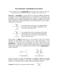
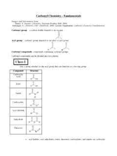
5 The electrodes are set into an epoxy resin disc (A) with the platinum cathode (B) at the centre of a dome surrounded by a well that contains the silver anode (C). When set up a uniform electrolyte layer is held over the dome area of the Electrode by a paper spacer and (polytetrafluoroethylene) membrane which is secured by an O-ring around the dome. The well that houses the anode also serves as a reservoir with electrolyte drawn up to the cathode by the paper spacer acting as a wick. An outer O-ring groove (D) surrounds the whole apparatus. The outer O-ring seals the electrodes into the base of an Electrode Disc oxygen Electrode is a specialised form of electrochemical cell which consists of two electrodes immersed in an electrolyte solution. Typically, a 50% saturated solution of KCl is used in oxygen Electrode systems.
6 This is prepared by dissolving of anhydrous salt in 100ml of de-ionised water at 25 C. Application of a polarising voltage of 700 mV ionises the electrolyte and initiates current flow via a series of electrochemical reactions. In the case of KCl electrolyte the following reactions occur: Oxygen is consumed during the electrochemistry, thus the magnitude of the current flow is related to the oxygen concentration of the surrounding media. This type of Electrode sensor was first developed by Clark (1956) to measure oxygen in blood samples. As a result it is often referred to as The Clark Electrode . Operational Principles. The following explanation are based around an Electrode disc which is connected to one of the Hansatech Instruments Ltd PC operated Electrode control units. For further details, please refer to the Oxygraph Electrode Control Unit Manual (supplied with the Oxygraph Control Unit).
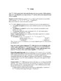
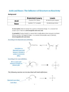
7 When the disc is correctly prepared and polarised at 700 mV, the nature of the electrochemical reactions at the disc cause a current to flow in the presence of oxygen. 4 CBADThis current is directly proportional to the amount of dissolved oxygen within the sample held in the reaction vessel. The electronics within the control unit must take the current produced by the Electrode disc and convert it into a reproducible unit. Several stages are taken applying various factors to the signal in order to present the signal from the disc as nmol/ml in liquid-phase measurements and mol RTA (relative to air) in gas-phase measurements. The diagram below shows the processes undertaken by the control unit in order to present the signal in calibrated units. In this example, the disc is placed in a stirred sample of air-saturated, de-ionised water held at 25 C at a standard atmospheric pressure of KPa.
8 The current produced by the electrochemical reactions in the presence of oxygen is first converted into a voltage signal. In air-saturated, de-ionised water, the control unit is designed to read approx. 2000 mV (approximately half the range of the instrument). Gain and Back Off are applied to the signal at this point. These values are automatically set during the calibration. However, these values always remain at Gain = approx. and Back off = 0. In cases where measurements of small changes in oxygen are required, these values may be manually adjusted. The voltage signal is then passed through the 12 bit resolution A/D converter where the signal is digitised. Once digitised, the calibration offset and factor are applied to the signal allowing the signal to be displayed in the relevant calibrated to the nature of the reactions taking place, the silver anode oxidises slowly with time.
9 This is characterised by a black deposit on the Electrode which may impair performance. If this occurs, the Electrode should be cleaned. This is best achieved by gentle polishing of the unit using the materials supplied in the S16 Electrode Maintenance KIT or if this is unavailable, by using a suitable polishing paste or fine grade aluminium oxide powder suspended in a drop of de-ionised water placed on a cotton wool bud. 5 NEVER USE HARSH ABRASIVE AGENTS OR COMMERCIAL METAL POLISHES AS THESE MAY DAMAGE THE RESIN OR IRREVERSIBLY POISON THE detail on cleaning and maintaining the Electrode disc can be found in the Electrode Maintenance section. Before use, the Electrode disc needs to be prepared in such away that an electrolyte bridge is formed between the anode and cathode in order for current to flow in the presence of oxygen.
10 Various different compositions of electrolyte have been used however, a 50% saturated solution of potassium chloride works well in many different applications. The solubility of the anhydrous salt is 35g per 100g of water at 25 C. Hence the electrolyte solution is easily made by dissolving of anhydrous salt in 100 ml of de-ionised water at 25 disc also requires a protective membrane which will prevent any deposits from the reaction mixture from settling on the cathode yet allow oxygen to diffuse freely so as not to jeopardise response time of the disc. There are four Preparation stages: Stage 1. Place a small drop of electrolyte on top of the dome of the Electrode disc. Stage 2. Place a sq. cm paper spacer (cigarette paper works particularly well as it is manufactured to a very tight thickness tolerance) over the electrolyte ensuring that at least one corner of the spacer is in the Electrode well to act as a wick.