Transcription of Electronic Controls - Eaton
1 Eaton Screw-In Cartridge valves E-VLSC-MC001-E December 2009 Eaton Brand CWhere measurements are critical request certified drawings. We reserve the right to change specifications without * SeriesFor use with valve types:EPV**-12D-1*EFV1-**-012DE*ERV1/2** -12D-1*EPRV1**-12D-1*Note: This product has been designed and tested to meet specific standards outlined in the European Electro-magnetic Compatibility Directive (EMC) 89/336/EEC, amended by 91/26/EEC, 92/31/EEC and 93/68/EEC, article 5. For instructions on installation requirements to achieve effective protection levels, see this leaflet and the Installation Wiring Practices for Vickers Electronic Products leaflet 2468. Wiring practices relevant to this Directive are indicated by a warning symbol and Electromagnetic Compatibility (EMC).
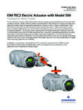
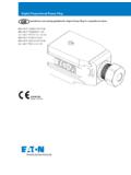
2 Electronic ControlsProportional Valve Control Power Plugs0V24V DCPo wer inputPo we p*+ + ?Electrical Block DiagramEHH-AMP-702-D/J/K-2** Type J does not have the ramp applications are in the control of non-feedback proportional valves where the cost of more sophisticated Electronic Controls can be J is typically used in closed-loop applications. General DescriptionThree types of plugs, conforming to ISO 4400/DIN 43650 interface, with integral amplifiers and necessary adjustment potentiometers, are designed for use with non-feed back hydraulic plug/valve combination offers very low cost solutions to many hydraulic control problems requiring proportional D is controlled with a 0-10V command signal, and has adjustable gain, ramp, deadband compensation and J, designed for closed-loop applications, is controlled with a 0-10V command signal, and has no ramp K is controlled with a 4-20 mA command signal, and has an adjustable ramp time of 50 ms to and Benefits Integral amplifier provides essential functions for control of proportional valves Adjustable ramp time (types D and K)
3 , gain, deadband compensation and dither Ease of installation, with reduced cost Fully short-circuit and reverse-polarity protected Differential voltage command signal (types D and J) Adjustable dither EMC to latest European standards Protection to IP67 Eaton Screw-In Cartridge valves E-VLSC-MC001-E December Eaton Brand CWhere measurements are critical request certified drawings. We reserve the right to change specifications without *22*Model Code/ Operating DataModel Code1 Adjustment RangeD - Proportional plug: 0-10 VDC with rampJ - Proportional plug: 0-10 VDC without ramp function K - Proportional plug: 4-20 mA with rampEHH AMP 702 2 Design Number20 SeriesSubject to change. Installation dimensions unaltered for design numbers 20 to 29 DataMechanicalHousing PA6 glass-reinforced plastic (conforming to UL-94HB).
4 Color: grayMounting interface ISO 4400 (DIN 43650)Cable clamp Pg9 screw typeCable diameter 5 to 10 mm ( to dia.)Wire section 0,5 to 1,0 mm2 (20-17 AWG)Temperature, ambient range -20 to +70 C (-4 to +158 F)Mass 0,07 kg ( lb)Electrical Types D and J Type KConnections 1 24V DC 2 OV (power and signal) 3 Positive command signal 4 Negative command signalPower (input) supply 20-30V DC including 10% maximum ripple (peak-to-peak) 24V DC nominalAbsolute maximum voltage 40V Max. power consumption 35W including solenoidReverse polarity protected YesShort circuit protected YesMaximum output current 1,6 AMaximum output voltage typical Typically 1,5V below supply voltage (1,6A output current)Command signal 0-10V (10 kohms) 4-20 mA (250 ohms)Deadband triggering 200 mV 4 mA For output (LED on) 200 mV to 10V 4-20 mA For no output (LED off) 0 mV to 100 mV 0-4 mADeadband adjustment range 100 to 1000 mAGain adjustment range to A/mA to A/mADither adjustment range 0 to 500 mARamp time (types D and K only) 50 ms to 5sPWM frequency 1200 Hz 10%Dither frequency 120 Hz 10%Protection IEC 529.
5 IP67 (when correctly installed with interface seal in place) Fully short-circuit and reverse-polarity protectedIsolation to VDE 0110 Group B Electromagnetic compatibility (EMC): Emission EN 50081-2 Immunity EN 50082-2 Eaton Screw-In Cartridge valves E-VLSC-MC001-E December 2009 Eaton Brand CWhere measurements are critical request certified drawings. We reserve the right to change specifications without CharacteristicsInstallation Dimensionsmm (inch)10V8V6V4V2V10V8V6V4V2 VCommand signalCommand signalvol tag eOutputcurrentOutputcurrentRam psettingTimeTimeTimeTimeDeadband compensationDeadband compensationSU XGain settingSU XGain setting20 mA12 mA4 mATyp e KTyp e DTyp e JTyp e K and DUsSolenoid Connections3rd angle projection1288 ( )39( )22( )34 (1.)
6 34)38( )No connection1 (or 2)2 (or 1)10V8V6V4V2V10V8V6V4V2 VCommand signalCommand signalvol tag eOutputcurrentOutputcurrentRam psettingTimeTimeTimeTimeDeadband compensationDeadband compensationSU XGain settingSU XGain setting20 mA12 mA4 mATyp e KTyp e DTyp e JTyp e K and DUsSolenoid Connections3rd angle projection1288 ( )39( )22( )34 (1 .34)38( )No connection1 (or 2)2 (or 1)Installation DataEATON Screw-In Cartridge valves E-VLSC-MC001-E December Eaton Brand CWhere measurements are critical request certified drawings. We reserve the right to change specifications without time: Turn clockwise to increase ramp time (Only types D/K).Gain: Turn clockwise to increase compensation: Turn clockwise to increase deadband compensation : Turn clockwise to increase the dither 1: Power Supply 20V-30V DC, 2: Power Supply 3: Command signal positive (see Operating Data ).
7 Terminal 4: Command signal negative (see Operating Data ).Installation Wiring OptionsInstallation Data1234 LEDD itherDeadbandGainRam pPo sitiv e Command Vo lta ge123424V0V0V123424V0V0V+10V 10 VEHH-AMP-702-D/J-20 EHH-AMP-702-D/J-20123424V0V0 VEHH-AMP-702-K-204-20 mANegative Command Vo lta ge4-20 mA Command Signal123424V0V0V123424V0V0V 10V+10 VEHH-AMP-702-D/J-2 EHH-AMP-702-D/J-2Bi-polar Command Volt age f or OperatingTw o Solenoids from One SignalPr otective ground when replacing 10 design power plugwith 20 design and only 3 wires ex ist123424V0V0 VEHH-AMP-702-D/J/K-Link pin 2 to 1234 LEDD itherDeadbandGainRam pPo sitiv e Command Vo lta ge123424V0V0V123424V0V0V+10V 10 VEHH-AMP-702-D/J-20 EHH-AMP-702-D/J-20123424V0V0 VEHH-AMP-702-K-204-20 mANegative Command Vo lta ge4-20 mA Command Signal123424V0V0V123424V0V0V 10V+10
8 VEHH-AMP-702-D/J-2 EHH-AMP-702-D/J-2Bi-polar Command Volt age f or OperatingTw o Solenoids from One SignalPr otective ground when replacing 10 design power plugwith 20 design and only 3 wires ex ist123424V0V0 VEHH-AMP-702-D/J/K-Link pin 2 to WARNINGE lectromagnetic Compatibility (EMC) - Screened cables should be used and particular attention paid to the grounding of the screens as shown in the above diagrams. AdjustmentsEATON Screw-In Cartridge valves E-VLSC-MC001-E December 2009 Eaton Brand CWhere measurements are critical request certified drawings. We reserve the right to change specifications without ( )Wi ring Preparation40 ( )4 x mm(20 AWG-1 7 AW G ) 5-10 ( dia**2*All seals must be fitted correctly at plug installation to provide protection to IP67 (IEC 529).)
9 Assembly Showing Wiring Connection PointsInstallation DataWARNINGE nsure cable clamp nut is adequately tightened to secure cable. Do not connect, or disconnect, the plug while power is on. Do not mount, or dismount, the plug while power is on. Eaton Screw-In Cartridge valves E-VLSC-MC001-E December Eaton Brand CWhere measurements are critical request certified drawings. We reserve the right to change specifications without DataStart-Up Procedure Correctly wire the plug and, before mounting it on the valve solenoid, apply 24V DC (20 to 30V limits) to the power input terminals. Check for correct plug function by illumination/ non-illumination of the LED. The LED should illuminate when the demand applied to the signal input terminal is between 200 mV and 10V (or 4 mA and 20 mA) and should not be illuminated when the applied demand is less than 100 mV (4 mA).
10 If there is a malfunction a new plug must be fitted. Switch off power supply and command/input signal and then install plug on solenoid. Ensure that all seals are fitted correctly and clamped as the retaining screw is tightened: this is essential in providing IP67 protection. Ensure that the hydraulic system will not cause any erratic movement of actuators, then: Switch on power supply again. Repeat LED/function check as in 2. An LED malfunction now indicates a short circuit at the load. Successful completion of these checks means that the plug and load are ready for PartsThe only spare part available is the interface seal, part number ProcedureOrder plug by full model code, and spare interface seals by part number Screw-In Cartridge valves E-VLSC-MC001-E December 2009 Eaton Brand CWhere measurements are critical request certified drawings.