Transcription of Engine Shutdown Installation Instructions R4020, …
1 ISSPRO, INC. 2515 Riverside Way, Portland OR 97211. Telephone: (503) 288-4488 Toll Free: (800) 888-8065. FAX: (503) 249-2999. Engine Shutdown Installation Instructions r4020 , r4020 -24 VDC (Complete Kit with 30 second delay control box). R4021, R4021-24 VDC (Complete kit with zero delay control box). R4022, R4022-24 VDC (Control box only with 30 second delay, used in r4020 kit). R4023, R4023-24 VDC (Control box only with zero delay, used in R4021 kit). Please read completely before beginning your Installation ! When voltage is referred to in the directions it means either 12 volts or 24 volts DC, depending on the unit you have purchased Systems and Shutdown in General There are two different types of Shutdown systems that can be purchased for Engine protection. Failsafe Systems These ISSPRO Electronic Engine Protection Systems are NOT of this type.
2 A failsafe system will cause Engine Shutdown should any part of the Shutdown system fail ( broken wires, faulty sensors, malfunctioning control box, etc.) While this is desirable, especially for unattended engines, it is costly to implement and can also inconvenience operations if there is actually nothing wrong with the Engine operation. However, a regularly tested and inspected non-failsafe system, such as provided by ISSPRO, will give reliable security for your Engine for many years. Non-Failsafe Protection Systems ISSPRO Electronic Engine Protection Systems are of this type. They have been well designed to provide the maximum in Engine protection at a reasonable price. ( There is no protection against failure in the wiring or sensors, connected to the ISSPRO control box. How They Operate r4020 and R4022 with 30 second delay: When ignition is turned on, the control box is powered by the vehicle electrical system.)
3 When the Engine is started, the alarm will be on until sufficient oil pressure is built up to overcome the oil pressure switch. After normal operating conditions have been established, should an Engine fault occur, such as low water level, low oil pressure, high water temperature, etc., the alarm will sound immediately. If the fault condition continues for longer than 30 seconds, the control box activates and shuts down the Engine . At any time, the unit can be reset by turning the ignition off and then back on again. R4021 and R4023 with Zero Delay for Stationary Engines: After ignition on, there is a 15 second period before the Shutdown system is active to enable the Engine to build oil pressure. Any time after the 15 second period has passed, if a fault is detected or present, the Shutdown device relay will activate immediately.
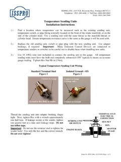
4 If oil pressure does not build up quickly enough, the ignition can be switched off to reset the unit, and then on again to begin another 15 second period. Other times are available, contact ISSPRO for standard options. Begin Installation : Mount the control box in a protected area away from heat sources, water or splash areas. On trucks, the preferred area is in the cab under the dash. The control unit does not have to be grounded. It should be securely fastened using the mounting tabs provided on the control unit. Low Water Level Probe Installation : 1. TOP TANK RADIATORS: Locate a point on the side of the tank away from the hose connections, but near the center of the tank, and above the core. (Fig. 1A) (The probe may also be mounted at the centered top of the tank, providing the bottom of the probe reaches sufficiently into the water.)
5 Be sure that the probe does not touch the top of the core, when fully inserted.) (See Fig. 1B). Form No. IS051 - (10/31/00 Rev. B) Page 1 of 5. 2. SIDE TANK RADIATORS: Locate a point on the side tank to give adequate warning. (See Fig. 2). 3. For aluminum and stainless steel tanks with a wall thickness of 1/8 or greater, drill a 7/16 hole at selected point and tap for (For thin wall brass radiators drill a 5/8 hole and silver solder the supplied brass bushing.). 4. Apply silicone sealant to the probe threads and screw the probe firmly into the tapped hole. 5. If the water level warning is not going to be used with the Shutdown , then it is necessary to jumper the water level probe input to the negative ( - ) terminal. (**See wiring diagram.) Failure to follow this procedure will cause the Shutdown to work improperly. This system will not work correctly if the radiator is not grounded or if the radiator has plastic tanks.
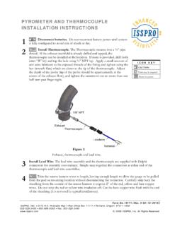
6 Please consult ISSPRO for assistance. 6. When wiring the probe to the control box you may also install an optional test switch as shown in the diagram. Install Alarm Devices: The alarm terminal of the control box operates by switching the alarm device internally to ground when the alarm switches connected to input 1, input 2, or low water level probe are activated. Connect either a buzzer or light or both to this terminal as shown in the wiring diagram. If you don't want to have an indicator, this terminal can be left unused. Please note that ISSPRO recommends use of only our Part # R7074 for the buzzer and R7051 for the light. Warning . Audible alarm devices of the electro-mechanical type should not be used ( Bells, Buzzlights, Nartron Buzzers, etc.). These devices cause interference that could affect the operation of the Shutdown system.
7 Maximum current load is 1 amp at this terminal. We recommend that a 1 amp fuse be placed in line prior to the alarm devices (see diagram) to protect this circuit from damage. Do not apply voltage to this terminal unless a light or buzzer is in the circuit. Damage will result without the presence of the light or buzzer if power is applied directly to the alarm terminal. Install & Connect Engine Alarm Switches: Terminals marked (1) and (2) are for the switches that will tell the control box to activate the Shutdown system. Some vehicles have existing switches for indicator lamps that may be used. For example, if your truck has a warning light to indicate that oil pressure is low, you will be able to connect to this oil pressure witch to activate the alarm. If the switch closes a circuit to ground when activated, it can be used to activate the ISSPRO system.
8 See the wiring diagram for some of the possibilities you may encounter. ISSPRO also supplies kits, which include these switches for low oil pressure and high temperature. (Also shown in diagram) Install the switches you will use and connect to terminals 1 or 2 or both. As many switches as you need can be used, as long as they are wired in parallel as shown and switch to ground on alarm condition. If you wish to set up a quick test switch for your system, you should install the optional switch as shown in the wiring diagram now. This will allow you to check the functionality of the system by just flipping a switch. It can also be used as a manual Shutdown , if desired. Install & Connect Shutdown Device: Two terminals are provided to drive your Shutdown device. These are the N/O (Normally open) and N/C (Normally closed) connections.
9 These are rated for a maximum load of 20 amps. Your solenoid, ignition coil, or rack puller should not draw mare than this 20 amps maximum. The N/O terminal will provide a positive voltage to the device when the control box functions. The N/C terminal will disconnect the positive voltage when the control box functions. See diagram for standard connection options. Connect a wire between your device and the correct terminal. Make sure to use wire which is large enough to carry the load of your system. Also make sure that a good ground connection for your device exists. Note: Negative Ground Only!!! You should now have the bottom (six terminal) side of your control box completely wired. We have instructed you to wire this side of the unit first because none of the connections you have made should have involved an application of power to the unit up to this point.
10 Although internal protection is built into the control box to prevent accidental damage Form No. IS051 - (10/31/00 Rev. B) Page 2 of 5. due to incorrect wiring, it is possible to damage any electronic device by applying power to its connections improperly. Please make sure that when you connect any wire that it does not come into contact with other wires or components. Read all directions carefully to insure that you don't damage the unit and void your warranty because of incorrect Installation . Power and Ground Connections Please note on the op (three terminal) side of the control box that there are three connections to be made. The numbers 1. and 2 shown on the diagram at this point, indicate that you have a choice to make when hooking up the common wire. For MOST installations, connection #1, shown with a solid line, should be made, connecting the common terminal to the positive voltage input of the unit.