Transcription of FUEL LEVEL GAUGE INSTALLATION INSTRUCTIONS
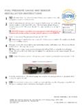
1 fuel LEVEL GAUGE INSTALLATION . INSTRUCTIONS . Models: R11900 R12900 R13900 R14900 R15900 R16900. R17900. Disconnect batteries. Do not reconnect battery power until 1 system is fully configured to avoid risk of shock or fire. ICON KEY. CAUTION. 2 Connect the sensor to the sensor harness by pressing the connector into the slot. Tools may be required Shown in picture 3 Route the sensor harness to the intended GAUGE mounting location, using grommets as appropriate when passing through the firewall. Connect the sensor harness to the GAUGE connector as follows: 4 Trim wires to desired length. The green and black wires are the sensor and ground connection, and connect to cavities 5 and 6 of the orange connector respectively (see Figure 1).
2 Install the two wires into the insulation displacement connector (orange connector). Carefully lay the wires across the connector cavities, hold the connector steady with a vice or pliers and press the wires into each cavity with a small screwdriver. Each wire must be pushed completely to the bottom of its groove in the connector, to ensure a good electrical connection. 5 An optional wiring harness is available (ISSPRO P/N R72022) to simplify wiring and provide a potentiometer for reducing the brightness of the GAUGE lights while still following the vehicle dimmer LEVEL . If this dimming function is not required, you can substitute your own 18 GAUGE wires in place of the harness, using a single wire in place of the orange and orange/black wires.
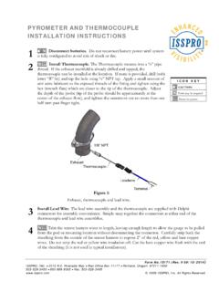
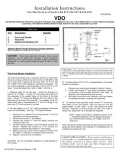
3 Connect one end of each of these wires as follows: Ground The black wire should connect to a clean ground on the vehicle such as the battery negative terminal or a factory ground bolt. Figure 1: Connector. Ignition The red wire should be connected to a circuit that 1 Red Ignition switches on with the key switch. 2 Orange Dimmer 3 Black Ground Wire should be fused so as not to exceed 3 amps. If the circuit does not have a fuse, or the existing fuse is higher than 3 amps, use 4 Empty 5 Green Sensor an inline fuse. 6 Black Ground Dimmer Connect the orange/black wire to the factory GAUGE dimmer circuit by either tapping into the in-cab fuse block or by connecting directly to the wire running from the dimmer on the headlight switch.
4 Form No. IS174 (Rev. C 12/09/2008). ISSPRO, INC. 2515 Riverside Way Post Office Box 11177 Portland, Oregon 97211-1899. 503-288-4488 800-888-8065 Fax: 503-249-2999. 2008 ISSPRO, Inc. All Rights Reserved. Connect the red, orange and black wires to the orange connector as described above, in positions 1, 2, and 3 respectively. Slide the white dust cover over the orange connector once the wires are securely installed. NOTE: The GAUGE backlighting will only illuminate if both the ignition supply AND the backlighting circuits are on. The lighting harness is designed to be used with Performax EV gauges. DO NOT. attempt to use this harness and potentiometer with any other GAUGE types.
5 OPTIONAL: Daisy Chain Your Gauges If multiple Performax EV2 gauges are being installed in one location (such as a pod), you may use a single set of the Ignition, Ground, and Dimmer wires to connect all of the gauges. Simply pass the wires from one orange connector to the next one in a daisy chain configuration. 6 Install the connector onto the back of the GAUGE (angled portion on end of connector pointing up as in Figure 1), and then secure the GAUGE in its mounting location. If drilling a mounting hole in a panel to mount this GAUGE , the hole size should be . Mounting Kit R19999 is available for larger mounting holes up to . Secure all wiring so that it does not interfere with moving parts or chafe on sharp edges.
6 This 7 may be accomplished by routing the wiring within the factory wire harness sheath, using wire ties and sheathing, and using appropriate grommets when passing through the firewall. Form No. IS174 (Rev. C 12/09/2008). ISSPRO, INC. 2515 Riverside Way Post Office Box 11177 Portland, Oregon 97211-1899. 503-288-4488 800-888-8065 Fax: 503-249-2999. 2008 ISSPRO, Inc. All Rights Reserved.