Transcription of Installation Instructions - davidsonsalesshop.com
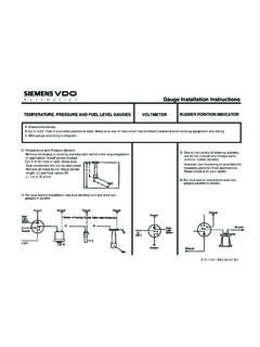
1 Installation Instructions For The fuel Level Sender Kit P/N 226 007 & 226 008 0 515 010 190 VDO THE Instructions FOR THE Installation OF THE BASIC fuel SENDER KIT FOLLOW. USE IS RESTICTED TO 12 VOLT NEGATIVE GROUND ELECTRICAL SYSTEMS FOR WIRING Instructions , REFER TO THE fuel gauge Installation . Parts Lists 0 515 0101 fuel Level Sender 11/09 Item Description Quantity 1. fuel Level Sender 1 2. Float Arm 1 3. Gasket and Hardware Kit 1 Additional Material Possibly Required to Complete Installation Bolt-On Installation Kit (optional) P/N 226 451 CAUTION: Read these Instructions thoroughly before making Installation .
2 Do not deviate from assembly or wiring Instructions . Always disconnect positive battery lead before making any electrical connections. If in doubt, please contact your dealer for VDO at 1-800-265-1818 CAUTION: When installing the float arm into the sender body, make sure the float ball is to the right side when you face the unit, as shown in Fig. 1. If installed to the left, the fuel gauge will read "full" when the tank is empty fuel Level Sender Installation The fuel Level Sender has a resistance rating of 0 ohms when the tank is empty and 90 ohms when full for p/n 226 008 or 240 ohms when tank is empty and 33 ohms when full for p/n 226 007.
3 Refer to the VDO catalog for matching fuel gauges. The unit can be adjusted to read accurately in tanks from 6" to 23" deep. For sender adjustment, refer to Table 1 and Fig. 2. I. Measure depth of the fuel tank. Locate the dimension in Column "A" of Table 1. Column "B" then shows the length from the underside of the sender flange to the center to the float pivot. Column "C" shows the distance from the center of the float pivot to the center of the float ball. For example, a tank 12" deep would need a measurement of 6" from the flange to the pivot, and " from the pivot to the float.
4 II. For tank depths up to 15 1/2" it will be necessary to eliminate a part of the assembly. (See Fig. 1) Proceed as follows: 1. Remove nut "a', washer "b" and ring terminal "c" from the underside of the mounting flange. 2. Remove two screws "d" and discard. 3. Remove two screws "e" from the plastic housing and reserve for later use. 4. Carefully remove bracket "f" from the plastic housing and discard. Replace with bracket "g" in the housing and loosely re-install the two screws "e" into housing.
5 5. Slide housing up or down until the proper dimension from the Table 1 is reached, then tighten screws securely. 6. Replace ring terminal and hardware. CAUTION: Do not over-tighten hardware, to avoid damage to the threads. III. For tank depths of 16" to 23", no disassembly for the sender bracket is necessary. 1. Remove ring terminal as instructed in Section II above. 2. Loosen two screws "d'" and adjust the plastic housing up and down until the proper dimension from Table 1 is obtained, then retightened screws securely.
6 3. Re-install ring terminal and hardware, and then tighten all hardware securely, avoiding over-tightening. IV. To install the float assembly, loosen screw "h", remove the short piece of rod, and discard. Insert the float rod until the proper length "c" from Table 1 is met, then tighten the screw securely. Carefully cut off any excess rod with a bolt cutter or similar tool, taking care not to damage the assembly NOTE: Make sure the float is installed as shown in Fig 1.
7 If installed backwards, the fuel gauge will indicate "full" when the tank is empty, and "empty" when the tank is full. VDO Instruments recommends that the fuel sender and the fuel gauge be wired together and checked for compatibility prior to installing fuel sender into tank. SAFETY PRECAUTION: When making modifications to fuel tanks, it is essential that the tank be removed from the vehicle, and that it is empty, clean, and dry. After drilling, make sure all chips and other foreign matter have been removed from the tank 0 515 0101 fuel Level Sender 11/09 Merchandise warranted against defects in factory workmanship and materials for a period of 24 months after purchase.
8 This warranty applies to the first retail purchaser and covers only those products exposed to normal use or service. Provisions of this warranty shall not apply to a VDO product used for a purpose for which it is not designed, or which has been altered in any way that would be detrimental to the performance or life of the product, or misapplication, misuse, negligence or accident. On any VDO part or VDOproduct found to be defective after examination by manufacturer, manufacturer will only repair or replace the merchandise through the original selling dealer.
9 Manufacturer assumes no responsibility for diagnosis, removal and/or Installation labor, loss of vehicle use, loss of time, inconvenience or any other consequential expenses. The warranties herein are in lieu of any other expressed or implied warranties, including any implied warranty of merchantability of fitness, and any other obligation on the part of manufacturer, or selling dealer.(NOTE: This is a "Limited Warranty" as defined by the Magnuson-Moss Warranty Act of 1975.)Merchandise warranted against defects in factory workmanship and materials for a period of 24 months after purchase.
10 This warranty applies to the first retail purchaser and covers only those products exposed to normal use or service. Provisions of this warranty shall not apply to a VDO product used for a purpose for which it is not designed, or which has been altered in any way that would be detrimental to the performance or life of the product, or misapplication, misuse, negligence or accident. On any VDO part or VDOproduct found to be defective after examination by manufacturer, manufacturer will only repair or replace the merchandise through the original selling dealer.