Transcription of Instrument Kit Installation and Wiring Instructions
1 Page 1 Part #0 515 010 396 Rev. 11/95 THE Instructions FOR Installation AND ELECTRICAL Wiring FOR THE Instrument KIT FOLLOWS. USE IS RESTRICTED TO 12 VOLT NEGATIVE GROUND ELECTRICAL and Materials Needed For Installation :18 gauge stranded, insulated wireInsulated " spade terminals2 1/16" and 31/8" or 33/8" hole sawsDrill and drill bit setBolt cutter or similar toolHalf-round fileTape measure or rulerWrench or nut driver setPhillips screw driverUtility knifeGas-proof gasket sealantWeld-on Installation Kit (optional) P/N 226 901 Bolt-on Installation Kit (optional) P/N 226 451 Optional VDO Mounting Bracket (speedometer only)1. Select mounting locations for all gauges which provide goodvisibility for the driver.
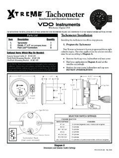
2 Lay out center points for each instrumenton the Information:These kits come with VDO s Spin-Lok Mounting Clamps for easyinstallation. Optional VDO mounting brackets are available fromyour VDO dealer, should you require them. Note that the pro-grammable speedometer included in this kit has a special set of in-stallation and operation Instructions . These Instructions must befollowed carefully to insure proper performance of the Installation :ItemDescription Speedometer (3c" or 3d" diameter) (21/16" diameter) gauge (21/16" diameter) gauge (21/16" diameter) gauge (21/16" diameter) Sender (d" 27 NPT) Sender (d" 18 NPT) Level Mounting Clamp for gaugesand Kit Installation Installation " 18 NPT to " 14 NPT adapter1 Parts List2.
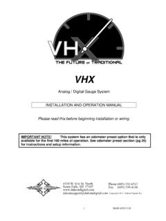
3 Cut 2 1/16" (52 mm) diameter holes for the smaller gauges. Placeeach gauge into its hole to be sure it fits. If the fit is too snug, use afile to slightly enlarge the opening until the gauge fits Make sure each gauge is rotated properly in its hole, and is easyto read. Hand-tighten the gauges with the enclosed Spin-Lok Mounting Clamps until the gauges can no longer be rotated byhand in the panel. Diagram A shows a properly mounted Installation :PLEASE REFER TO THE SEPARATE PROGRAMMABLESPEEDOMETER Installation AND OPERATINGINSTRUCTIONS FOR PROPER MOUNTING AND OP-ERATION OF THE SPEEDOMETER. SEE PAGE 3 FORINSTRUCTIONS ON INSTALLING SPEED is best that you mount the speedometer after you have in-stalled the 21/16" (52 mm) gauges.
4 Illumination Wiring of thespeedometer and the 21/16" (52 mm) gauges should be doneat the same time. Other Wiring should be done in whateversequence is easiest for AProper mounting using VDO s Spin-Lok Mounting ClampDiagram BMounting with Optional Speedometer Mounting BracketInstrument Kit Installation and Wiring InstructionsFor Vision, Cockpit, Cockpit White, Cockpit Royale, Series 1, Heritage Gold and Industrial StylesVDOI nstrumentsCAUTION: Read these Instructions thoroughly before mak-ing Installation . Do not deviate from assembly or Wiring in-structions. Always disconnect battery ground before makingany electrical connections. If in doubt, please contact yourdealer or VDO Instruments at (540) , Virginia USA Minimum mounting depth2 7/8" (73mm)Minimummountingdepth3 9/16" (91 mm)Page 2 fuel Level Sender InstallationCAUTION: Do not overtighten hardware, to avoiddamage to the threads!
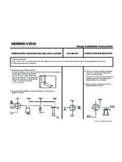
5 WDQN & % $ IOR DWIXHOOHY H OV H QG HUDiagram CMeasurements Needed To Make Proper AdjustmentsTABLE 1 (dimensions in inches) A B C A B C A B C fuel Level Sender has a resistance rating of 10 when thetank is empty and 180 when full. Refer to the VDO InstrumentsCatalog for matching fuel gauges. The unit can be adjusted to readaccurately in tanks from 6" to 23" deep. For sender adjustment,refer to Table 1 and Diagram Measure the depth of your fuel tank. Locate this dimension inColumn A of Table 1. Column B then shows the length fromthe underside of the sender flange to the center of the float C shows the distance from the center of the float pivot tothe center of the float ball.
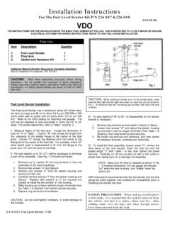
6 For example, a tank 12" deep wouldneed a measurement of 6" from the flange to the pivot, and "from the pivot to the For tank depths less than 15 " it will be necessary to eliminatea part of the assembly. Otherwise, proceed to Section III. Refer toDiagram D and proceed as follows:1. Remove nut a, washer b, and ring terminal c from the underside of the mounting Remove the two screws marked d and Remove the two screws marked e from the plas-tic housing and save for later Carefully remove bracket f from the plastichousing and discard. Replace it with bracket g in the housing and loosely re-install the two screwsmarked e into the Slide the housing up or down until the properdimension from Table 1 is reached, then tightenthe screws e Replace the ring terminal and its hardware.
7 !! IMPORTANT !!As received, the unit willhave a short lever arminstalled. Loosen the screwand remove the short leverarm, and replace it withthe long float arm andplastic float ball the Installation isfinished, the arm lengthto the left (short side) ofthe screw must be 1". Refer to Diagram E for Installation of the fuel sender assemblyinto the tank. The sender flange is designed to fit a standard SAEhole : Make sure the float is installed as shown in DiagramB. Remember, if it is installed backwards, the fuel gaugewill indicate FULL when the tank is actually empty, andvice-versa. Be sure to leave 1" on the short side of the To install the float assembly, loosen the screw marked h, re-move the short piece of rod, and discard it.
8 Insert the float rod untilthe proper length the C length from Table 1 is met, then tightenscrew h securely. Carefully cut off any excess rod with a bolt cut-ter or similar tool, taking care not to damage the For tank depths of 16" to 23", no disassembly of the senderbracket is Remove the ring terminal as instructed inSection II, Loosen the two screws marked d. Adjust theplastic housing up or down until the proper di-mension from Table 1 is obtained, then retightenthe screws securely. DO NOT overtighten Re-install the ring terminal and its , tighten the hardware securely, but DONOT DParts of the fuel Level Sender Unit to be AdjustedCAUTION: When attaching the float arm to the sender body,make sure the float ball is to the right side as you face the unit,as shown in Diagram D.
9 If you attach the float arm to the left ofthe sender body, or backwards, the fuel gauge will read FULL when the tank is actually empty!Page 3 CAUTION: Before drilling any holes into the tank, place thesender assembly on top of the tank to judge the proper holeplacement one that will allow the float arm clearance insidethe PRECAUTION: When making modifications tofuel tanks, it is essential that the tank be removed from thevehicle, and that it is empty, clean and dry. After drilling, makesure all chips and other foreign matter have been removed fromthe tank. Clean the tank no holes exist in the fuel tank (see CAUTION, above):1. Carefully mark an area to be cut open so you can insertthe sender.
10 The key to this step is to position the floatas close as possible to the center of the tank. This pro-vides the most stable and accurate reading when thefuel sloshes back and forth. Make sure you have al-lowed enough clearance for the float arm before you cutthe hole. Remember, you only get one chance to do itright!2. Cut a " (43 mm) hole in the top of the With the gasket in place below the flange, carefully feedthe float arm and sender body into the " (43 mm)hole in the tank. Make certain the float arm has freemotion within the tank. Using the sender flange as atemplate, locate the positions of the five mounting on the thickness of the tank, either self-tap-ping screws or #8-32 machine screws may be used, drill-ing and tapping accordingly.