Transcription of PYROMETER AND THERMOCOUPLE …
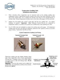
1 Form No. IS171 (Rev. H 09/10/2014) ISSPRO, INC. 2515 Riverside Way Post Office Box 11177 Portland, Oregon 97211-1899 503-528-3400 800-888-8065 Fax: 503-528-3495 2008 ISSPRO, Inc. All Rights Reserved. PYROMETER AND THERMOCOUPLE INSTALLATION INSTRUCTIONS I C O N K E Y CAUTION Tools may be required Shown in picture 1 Disconnect batteries. Do not reconnect battery power until system is fully configured to avoid risk of shock or fire. 2 Install THERMOCOUPLE . The THERMOCOUPLE mounts into a pipe thread. If the exhaust manifold is already drilled and tapped, the THERMOCOUPLE can be installed at the location. If none is provided, drill (with letter R bit) and tap the hole using NPT tap. Apply a small amount of anti seize lubricant to the exposed threads of the fitting and tighten using the hex (wrench flats) which are closer to the tip of the THERMOCOUPLE .
2 Adjust the depth of the probe (tip of the probe should be approximately at the center of the exhaust flow), and tighten the outermost nut no more than one half turn past finger tight. 3 Install Lead Wire. The lead wire assembly and the THERMOCOUPLE are supplied with Delphi connectors for assembly convenience. Simply snap together the connectors at either end of the THERMOCOUPLE and lead wire assemblies. 4 Trim the sensor harness wires to length, leaving enough length to allow the gauge to be pulled from the pod or mounting location without disconnecting the connector. Carefully strip back the sheathing from the outside of the sensor harness to expose 2 of the red, yellow and bare copper wires. Do not strip the red or yellow wire insulation off. Cut the bare copper wire flush with the end of the sheathing (it is not used in typical installations).
3 Figure 1: Exhaust, THERMOCOUPLE and lead wire. Form No. IS171 (Rev. H 09/10/2014) ISSPRO, INC. 2515 Riverside Way Post Office Box 11177 Portland, Oregon 97211-1899 503-528-3400 800-888-8065 Fax: 503-528-3495 2008 ISSPRO, Inc. All Rights Reserved. 5 Install the three sensor harness wires along with the individual red, orange and black wires into the orange in sulation displacement connector (see for positions), using the included wire insertion tool (R72023). Follow the directions with the tool. DO NOT strip the wire ends, the connector will pierce the wire insulation, and the insulation helps hold the wire into the connector. Each wire must be pushed completely to the bottom of its groove in the connector to ensure a good electrical connection. Connect the other end of each of the remaining wires as follows: Ignition The red wire should be connected to a circuit that switches on with the key switch.
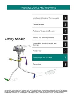
4 Wire should be fused so as not to exceed 1 amp. If the circuit does not have a fuse, or the existing fuse is higher than 1 amp, use an inline fuse. Dimmer Connect the orange wire to the factory gauge dimmer circuit by either tapping into the in-cab fuse block or by connecting directly to the wire running from the dimmer on the headlight switch. Ground The black wire in pin #3 should connect to a clean ground on the vehicle such as the battery negative terminal or a factory ground bolt. Figure 2: Connector. 1 Red Ignition 2 Orange Dimmer 3 Black Ground 4 Yellow [+] Sensor 5 Red [-] Sensor 6 Empty Slide the white dust cover over the orange connector once the wires are securely installed. NOTE: The gauge backlighting will only illuminate if both the ignition supply AND the backlighting circuits are on.
5 OPTIONAL: Daisy Chain Your Gauges If multiple EV2 gauges are being installed in one location (such as a pod), you may use a single set of the Ignition, Ground, and Dimmer wires to connect all of the gauges. Simply pass the wires from one orange connector to the next one in a daisy chain configuration. 6 Install the connector onto the back of the gauge (angled portion on end of connector pointing up as shown in photo), and then secure the gauge in its mounting location. If drilling a mounting hole in a panel to mount this gauge, the hole size should be . Mounting Kit R19999 is available for larger mounting holes up to . NOTE!!! The orange connector MUST be installed in the direction shown. It is possible to force it in backwards far enough to make an electrical connection, which will cause a short which may damage the gauge, wiring, sensor, or your vehicle!
6 8 Secure all wiring so that it does not interfere with moving parts or chafe on sharp edges. This may be accomplished by routing the wiring within the factory wire harness sheath, using wire ties and sheathing, and using appropriate grommets when passing through the firewall. Pin #6 Dimmer (orange) Ground (black) Ignition (red) Sensor [+] (yellow) Sensor [-] (red) Pin Numbers 1 2 3 4 5 6