Transcription of Enterprise Gateway Router with Gigabit Ethernet
1 Enterprise Gateway Router with Gigabit EthernetModel: USGI ntroductionThank you for purchasing the Ubiquiti Networks UniFi Security Gateway . This Quick Start Guide is designed to guide you through installation and also includes warranty terms. Package ContentsUniFi Security GatewayPower Adapter (12V, 1A)Power CordEnterprise Gateway Router with Gigabit EthernetModel: USGS crews (Qty. 2)Screw Anchors (Qty. 2)Quick Start GuideTERMS OF USE: All Ethernet cabling runs must use CAT5 (or above). It is the professional installer s responsibility to follow local country regulations and indoor cabling Controller System Requirements Microsoft Windows 8, Mac OS X, or Linux Java Runtime Environment (or above) Web Browser: Mozilla Firefox, Google Chrome, Microsoft Edge, or Microsoft Internet Explorer 11 UniFi Controller software or higher (available at.)
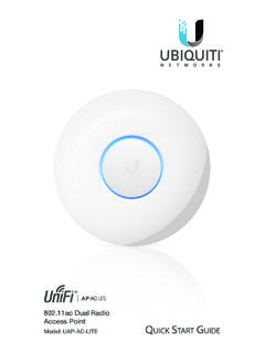
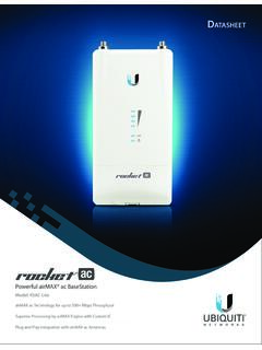
2 Network RequirementsA UniFi Cloud Key or management station running the UniFi Controller software, located either on-site and connected to the same Layer-2 network, or off-site in the cloud or NOCUS-16-150 WUSG(DHCP Server)InternetUAP-AC-PROUAP-AC-LRLANWAN UniFi Cloud Key(UniFi Controller)Remote Access toUniFi GB24 GUI RATECURRENT GHZCHANNELMbpsACTIVE DEVICEACTIVE DEVICESACTIVE ++ TESTI nactiveInactivePendingPendingInactivePen ding0000004040msec30msec20msec10msec0403 020100msecMbps30 Mbps20 Mbps10 Mbps0 Mbps24 UPLOADDEVICESCLIENTSWANU biquitiStreaming GB921 MB813 GB379 MBNetwork ProtocolsWeb / Web UpdateUnknownOtherNestLabsGoogleDesktop/ LaptopNASO therLANWLANDEEP PACKET INSPECTIONTHROUGHPUT& LATENCYAvg/Max ThroughputLatency12 HRSNOWHRS1361234222251840444852566064100 1041081121161201241281321361401441491531 571651612345678910111 Network DiagramAll UniFi devices support off-site management controllers.
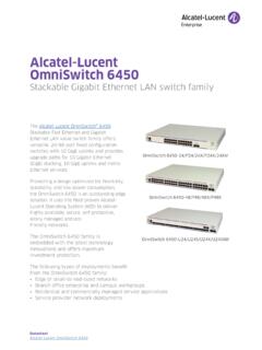
3 For setup details, see the User Guide on our website at: OverviewPorts PanelInterfaceDescriptionConsoleRJ45 serial console port for CLI management. Use a RJ45-to-DB9 serial console cable to connect the Console port to your computer. Then configure using the following settings: Baud rate 115200 Data bits 8 Parity NONE Stop bits 1 Flow control NONER esetResets to factory defaults. The UniFi Security Gateway should be powered on. Press and hold the Reset button for about 10 seconds until the right LED on the WAN 2 / LAN 2 port starts flashing and then becomes solidly lit. After a few seconds, the LED will turn off, and the UniFi Security Gateway will automatically reboot. WAN 1 Supports 10/100/ 1000 Ethernet WAN connections. Default setting is DHCP client.
4 LAN 1 Supports 10/100/ 1000 Ethernet LAN connections. Default setting is DHCP Server. Server IP: 2 / LAN 2 Supports 10/100/ 1000 Ethernet connections. Configure the port using the UniFi Security Gateway configuration IndicatorStatusWhiteFully Booted; Not AdoptedBlueAdopted and ProvisionedAlternating White/BlueDevice Firmware is UpgradingBlue FlashingDevice Locator Activated from UniFi ControllerConsolePowerOffPower OffGreenPower OnEthernet Speed/Link/ActOffNo LinkAmberLink Established at 10/100 MbpsAmber FlashingLink Activity at 10/100 MbpsGreenLink Established at 1000 MbpsGreen FlashingLink Activity at 1000 MbpsHardware InstallationThe UniFi Security Gateway can be used on a level, stable surface, or mounted to a wall with the included screws and anchors.
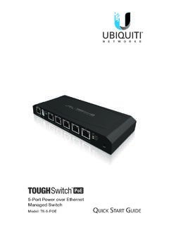
5 If you are not going to mount the UniFi Security Gateway on a wall, then skip to the section, Connecting : To reduce the risk of fire or electric shock, do not expose this product to rain or : FAILURE TO PROVIDE PROPER VENTILATION MAY CAUSE FIRE HAZARD. KEEP AT LEAST 20 MM OF CLEARANCE NEXT TO THE VENTILATION HOLES FOR ADEQUATE mount the UniFi Security Gateway on a wall, you will need a drill, a 6 mm drill bit, and a Phillips Use a 6 mm drill bit to drill two holes 90 mm apart. Insert a Screw Anchor into each mm*640-00120-04*640-00120-042. Use a Phillips screwdriver to secure a Screw into each anchor. Leave a clearance of approximately 3 mm between the screw head and the mm3. Position the UniFi Security Gateway over the Screws, and insert the Screws into the wall-mount slots located on the bottom of the UniFi Security Gateway .
6 Then slide the UniFi Security Gateway down to lock it into Power1. Connect the Power Adapter to the power Connect the Power Cord to the Power Adapter. Connect the other end of the Power Cord to a grounded power Connections1. Connect an Ethernet cable from a broadband modem or WAN to the WAN 1 Connect an Ethernet cable from a network switch to the LAN 1 : LAN 1 is set to DHCP Server by InstallationDownload and install the latest version of the UniFi Controller software at: a management station connected to the same Layer-2 network, launch the installer and follow the on-screen : If you already have UniFi Controller or higher installed, go to the section, Adopting the UniFi Security The Ubiquiti UniFi Controller window will appear. Click Launch a Browser to Manage the Select your country and time zone.
7 Alternatively, you can click restore from a previous backup to use a file that contains your backup settings. Click Next. 3. The UniFi Controller will discover the UniFi Security Gateway with the default IP Address, Select the device, and click Create an SSID (wireless network name) and Security Key. Click Next. If you do not have any UniFi APs on the network, click Create an Admin Name and Password for super admin access to the UniFi Controller. Confirm the Password, and click Review the UniFi Controller settings. Click Finish to complete the UniFi Setup The login screen for the UniFi Controller will appear. Enter the Admin Name and Password that you created in the UniFi Setup Wizard. Click UniFi Controller dashboard window will the UniFi Security Gateway1.
8 From the UniFi Controller dashboard, click Devices in the left menu In the Devices window, locate UniFi Gateway in the list of devices under the Model column. To adopt and provision the Gateway , click The Status Indicator on the UniFi Security Gateway will turn blue to confirm that it is successfully WAN Port Configuration via Layer 3By default, the WAN port is set to DHCP so it can be assigned network settings by the service provider. To change the setting, connect a computer directly (or through a switch) to the LAN 1 port of the UniFi Security Gateway . 1. From a web browser, go to The UniFi Gateway login window will appear. Enter your Username and Password. Click Sign : If the UniFi Security Gateway has not been adopted by a UniFi Controller, the login window will be skipped and the Setup window will In the Setup window, click Edit Configuration to configure the WAN port to DHCP, Static IP, or information on using the UniFi Controller software, refer to the User Guide located on our website at: Security GatewayDimensions135 x 135 x mm( x x ")Weight366 g ( oz)Networking Interfaces Serial Console PortData Ports(1) RJ45 Serial Port(3) 10/100/ 1000 Ethernet PortsMax.
9 Power Consumption7 WPower Supply12 VDC, 1A Power Adapter (Included)Supported Voltage Range9 to 24 VDC LEDsSystemSerial Console PortData PortsStatusPowerSpeed/Link/ActivityLayer 3 Forwarding PerformancePacket Size: 64 BytesPacket Size: 512 Bytes or Larger 1,000,000 pps3 Gbps (Line Rate)ProcessorDual-Core 500 MHz, MIPS64 with Hardware Acceleration for Packet ProcessingSystem Memory512 MB DDR2 RAMOn-Board Flash Storage2 GBRackmountYe sOperating Temperature-10 to 45 C (14 to 113 F)Operating Humidity10 to 90% NoncondensingCertificationsCE, FCC, ICSafety Notices1. Read, follow, and keep these Heed all Only use attachments/accessories specified by the : Failure to provide proper ventilation may cause fire hazard. Keep at least 20 mm of clearance next to the ventilation holes for adequate : To reduce the risk of fire or electric shock, do not expose this product to rain or moisture.
10 WARNING: Do not use this product in a location that can be submerged by water. WARNING: Avoid using this product during an electrical storm. There may be a remote risk of electric shock from lightning. Electrical Safety Information1. Compliance is required with respect to voltage, frequency, and current requirements indicated on the manufacturer s label. Connection to a different power source than those specified may result in improper operation, damage to the equipment or pose a fire hazard if the limitations are not There are no operator serviceable parts inside this equipment. Service should be provided only by a qualified service This equipment is provided with a detachable power cord which has an integral safety ground wire intended for connection to a grounded safety Do not substitute the power cord with one that is not the provided approved type.