Transcription of Ex-proof proportional valves with integral digital ... …
1 Assembly positionAny position Subplate surface finishingRoughness index, Ra 0,4 flatness ratio 0,01/100 (ISO 1101) Ambient temperatureSee section 1 FluidHydraulic oil as per DIN 51524 .. 535 for other fluids see model code sections Recommended viscosity15 100 mm2/s at 40 C (ISO VG 15 100) Fluid contamination classISO 4406 class 20/18/15 NAS 1638 class 9, in line filters of 10 mm (b10 _>75 recommended) Fluid temperature-20 C +60 C (standard seals) -20 C +80 C (/PE seals)2 MAIN CHARACTERISTICS OF Ex-proof proportional VALVESEx- proof proportional valves with integral digital driverswith or without integral position or pressure transducer - ATEX or IECEx certificationTable F650-4/EF650 DKZA-TES-* valve body Ex-proof solenoid Ex-proof position transducer Ex-proof electronics housing digital integral electronics Ex-proof cable glands (to be ordered separately) Ex-proof solenoid3 CERTIFICATION = ATEX identification for explosive atmospheresII = Group II for surfaces plants2 = High protection (equipment category)
2 G = For gas and vapoursd = Flame proof housingIIC= Gas groupT6/T5/T4/T3In the following are resumed the valves marking according to Atex 94/9/CE and IECExZone 1 Zone 2= Temperature class of solenoid surface referred tothe max ambient temperature= Possibility of explosive atmosphere during normal functioning= Low probability of explosive atmosphere WARNING:service work provided on the valve by the end users or not qualified personnel invalidates the certificationEx- proof ZA valves are proportional valvesequipped with specific solenoids and inte-gral digital electronic drivers available withfollowing certifications and protection mode: ATEX 94/9/CE Ex II 2 G Ex d IIC T6/T5/T4/T3 (group IIfor surface plants with gas or vapoursenvironment, category 2, zone 1 and 2) IECEx worldwide recognized safety certi-fication, Ex d IIC T6/T5/T4/T3 Gb IP66 The solenoid and the electronics housingare designed to contain the possibleexplosion which could be caused by thepresence of the gas mixture inside thehousing, thus avoiding dangerous propa-gation in the external environment.
3 Theyare also designed to limit the externaltemperature according to the certifiedclass to avoid the self ignition of theexplosive mixture present in the integral digital drivers in explosionproof construction provides consistentadvantages respect to the separated ana-log drivers for Ex-proof valves : compact execution simplified valve wiring reduced risk of electromagnetic distur-bances on the valve s transducer feed-back signal possibility to exploit in hazardous envi-ronment all the advantages provided bythe standard digital electronics: softwa-re setting of the main functional parame-ters as bias, ramps, scale, linearizationof the hydraulic regulation characteristic complete diagnostics of the driver sta-tus, and fault communication interfaces areavailable: PS, Serial communication interface forconfiguration, monitoring and firmwareupdating through Atos PC software.
4 BC, CANopen interface BP, PROFIBUS DP interfaceThe valves with BC and BP interfaces canbe integrated into a fieldbus communicationnetwork and thus digitally operated by themachine control Ex-proof digital integral electronics isavailable for the full range of proportionalvalves, as shown in the following certificationIECEx certificationEx II 2G Ex d IIC T6/T5/T4/T3Ex d IIC T6/T5/T4/T3 Gb IP661 EXPLOSION proof CERTIFICATION MAIN DATAVALVE TYPET emperature class(only for Group II)Surface temperatureAmbient temperatureDOUBLE SOLENOID valves (with or without transducer)SINGLE SOLENOID valves (with or without transducer)T4 135 C-20 +40 CT3 (option /7) 200 C-20 +60 CT6 85 C-20 +45 CT5(option /7) 100 C-20 +60 CMechanical constructionCable entrance and electrical wiringProtection degreeIP66 According to IEC 144 when correctly coupled with the relevant cable gland see section 22 Flame proof housing classified Ex d, according to EN 60079-0: 2006, EN 60079-1: 2007 Internal terminal board for cable connections threaded connection for cable entrance Note:This technical table contains information about Ex-proof certification data, model codes,dimensions and wiring of the Ex-proof proportional valves with integral digital detailed information about.
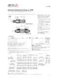
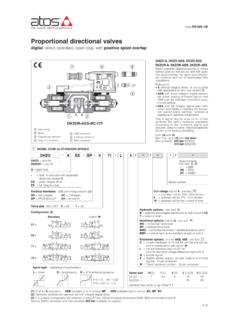
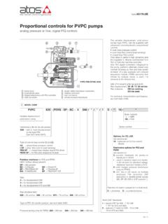
5 -valve s functional characteristics and mounting surface dimensions- digital drivers technical data and functional parameters settingsee the relevant technical tables of the standard proportional valves and digital = Equipment for explosive atmospheresd = Flame proof housingIIC = Gas groupT6/T5/T4/T3 = Temperature class of solenoid surfaceGb = Equipment protection level, high level protection for explosive Gas atmospheresIP66= Protection GROUP II, GROUP II, ATEXS eries numberDHZA = size 06 DKZA = size 10 AES = without integral position transducerTES = with integral position transducer Spool type:L = linearS = progressiveD = as S, but with P-A = Q, P-B = Q/24 MODEL CODE OF Ex-proof proportional DIRECTIONAL valves DIRECT OPERATEDC able entrance threaded connection:M = M20x1,5 (6H/6g)Options:7 = for ambient temp.
6 Up to 60 CB = solenoid with integral digitalelectronics at side of port AC = current feedback 4 20 mA forremote transducer, only for W(only AES)I = current reference 4 20 mA,omit for standard voltagereference 10 VDCW= power limitation function(only AES)Y = external drain//----/Spool size: see section 5 Communication interfaces:PS = Serial (1)BC = CANopenBP = PROFIBUS DPValve size (ISO 4401):0 = size 06 (DHZA)1 = size 10 (DKZA)5 HYDRAULIC CHARACTERISTICS of DHZA and DKZA (based on mineral oil ISO VG 46 at 50 C)Hydraulic symbols of AESversion*70*71*72*73*51*53*51/B*53/BHy draulic symbols of TESversion*70/B*71/B*72/B*73/BConfigurat ion: DHZA and DKZA see section 5:5 = external plus central position, spring centered7 = 3 positions, spring centeredSpool overlapping in central position, DHZA and DKZA see section 5:0= zero overlapping (only TES)1= P, A, B, T positive overlapping2= P, A, B, T positive overlapping (2)3= P positive overlapping; A, B, T, negativeNote: For mounting surface dimensions see table P005 For the digital drivers technical data and functional parameters setting, see: table G115 (AES); G210 (TES)(1) Serial interface always present for AES-BC and AES-BP.
7 (2) Only for DKZA-TES-172-S5 the spool overlapping type 2 provides the same characteristic of type 1, but in central position the internal leakages fromP to A and B are drained to tank, avoiding the drift of cylinders with differential drift (only TES)zero point displacement < 1% at DT = 40 C(1) Spool type S2 only for AES version; spool type 0L5, 0D5, 0L3 only for TES versionValve modelDHZA-AES DHZA-TESS pool type and size (1) Spool overlapping Max flow [l/min]at Dp = 10 bar (P-T) at Dp = 30 bar (P-T)at Dp max (P-T)Response time (2) [ms]Hysteresis [%]Repeatability< 30 (AES) < 15 (TES) 5%(AES) 0,2% (TES) 1% (AES) 0,1% (TES)< 40 (AES) < 20 (TES) 5%(AES) 0,2% (TES) 1% (AES) 0,1% (TES)1234,581245809060105120L14L1183045S 3, L3, D3285060S5, L5, D5S3, L3, D3S5, L5, D51, 31, 31, 31, 31, 31, 3(2) Response times at step signal (0% 100%)
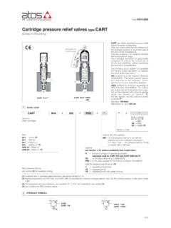
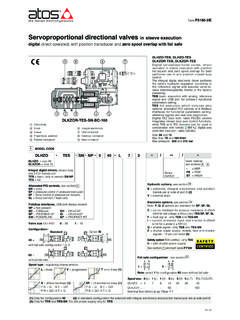
8 Are measured from 10% to 90% of step value and are strictly referred to the valve DKZA-TESP ressure limits [bar]ports P, A, B = 350; T = 160 (250 with external drain /Y)ports P, A, B = 315; T = 160 (250 with external drain /Y)Dp max P-T [bar]707050504040L5, D50L5, D50S5281421S2L30 Certification (omit for Atex):IE= IECEx*71*73*51*53*51/B*53/B*71/B*73/BSea ls material:- =NBR PE= FKM *DHZAIETESPS071L5M7**Spool size: see section 7F650 Series numberDPZA= size 10 =size 16 =size 25 AES= without integral positiontransducerSpool type:L = linearS = progressive D = as S, but with P-A = Q, P-B = Q/26 MODEL CODE OF Ex-proof proportional DIRECTIONAL valves PILOT OPERATEDC able entrance threaded connection:M = M20x1,5 (6H/6g)Options.
9 7 = for ambient temperature up to60 CB = solenoid with integral digitalelectronics at side of port AC = current feedback 4 20 mA forremote transducer, only for WD = internal drain E = external pilot G = pressure reducing valve forpiloting (2)I = current reference 4 20 mA,omit for standard voltagereference 10 VDCW= power limitation functionCommunication interfaces:PS = Serial (1)BC = CANopenBP = PROFIBUS DPValve size (ISO 4401):1 = size 102 = size 164 = size 25 Configuration: see section 7: 5 = external plus central position, spring centered7 = 3 positions, spring centeredSpool overlapping in central position, see section 7:1= P, A, B, T positive overlapping3= P positive overlapping; A, B, T, negativeNote:For mounting surface dimensions see table P005 For the digital drivers technical data and functional parameters setting, see table G115 (1) Serial interface always present for AES-BC and AES-BP.
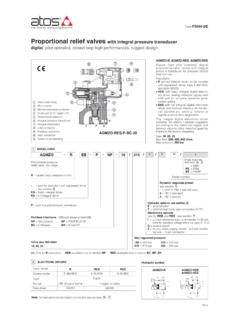
10 (2) Pressure reducing valve with fixed setting (40 bar for DPZA-1 and -2; 100 bar for DPZA-4) installed between pilot valve and main is advisable for valves with internal pilot in case of system pressure higher than 200 (omit for Atex):IE= IECEx*71*71/B*73*73/Baabbababbbaa*51*51/ B*53*53/B(1) Response times at step signal (0% 100%) are measured from 10% to 90% of step value and are strictly referred to the valve CHARACTERISTICS OF DPZA-AES (based on mineral oil ISO VG 46 at 50 C)Hydraulic symbols of AESversion4808309001602704002504305500, 1, 31001601800, 1, 30, 1, 3 Valve modelSpool overlappingSpool type and size (1) Max flow: [l/min]at Dp = 10 barat Dp = 30 barmax permissible flowDPZA-4 DPZA-2 DPZA-1L5S5D5S3D3L5S5D5L5S5D5 spool overlapping 1-3 Hysteresis [%]RepeatabilityResponsetime [ms] (1)Pressure limits [bar]ports P, A, B, X = 350; T = 250 (5 for optio)