Transcription of Features - GGB
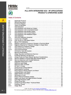
1 Model 40A probes mounted in three different adaptor stylesstructures. This reliable low resistancecontact is one of the keys to providinghighly repeatable measurements. TheModel 40A also provides direct viewingof the probe tips for accurate Model 40A can be mounted invarious adaptors for use with standardmicrowave probe stations or attached tothin blades for use with dc probe needleson a probe card or multi-contact mounts are GGB Industries, Inc., Model 40 APicoprobe sets new standards inmicrowave probing performance . Usinglow loss coaxial techniques, the Model40A achieves an insertion loss of less db and a return loss of greater than 18db through 40 its individually spring loadedBeryllium-Copper or optional Tungstentips, the Model 40A provides reliablecontacts, even when probing non-planarAny pitch (tip spacing) from 50 to 1250microns may be specified.
2 Probe pitchesgreater than 1250 microns can be accom-modated. The probe can be configuredwith Ground-Signal-Ground (G,S,G),Ground-Signal (G,S), or Signal-Ground(S,G) tip footprints. We recommendsmaller pitches with a G,S,G footprint forbest to the Model 40A is througha female K connector and is compatiblewith the mm and SMA INDUSTRIES INC. Model 40 AHigh PerformanceMicrowave ProbesFeatures Durable DC to 40 GHz Insertion loss less than db Return loss greater than 18 db Measurement repeatability -80 db Individually spring loaded contacts BeCu or Tungsten tips available Any pitch from 50 to 1250 microns Variety of Footprints Patented coaxial design Flexible Tips for Flexible ProbingEach Model 40A has patented, independently spring loaded tipswhich ensure a reliable contact to the probing surface. Becausethe tips are flexible they minimize circuit damage, increase probelife, and most importantly, provide a reliable individually springloaded contact for each point.
3 With a small amount of overdrive,the point scrubs the surface to make a reliable contact free of dust,dirt, and oxide contamination. The ability to view the exactcontact area eases probe positioning and allows for the precisepositioning necessary for good LRM calibrations. The flexibletips even allow probing of non-planar surfaces such as ceramicsubstrates and laser diode Transmission Improves PerformanceThe Model 40A uses a precision miniature 50 ohm coaxial cablefrom the probe tips to the connector interface. The coaxial designprovides lower loss and less radiation than coplanar designs. Theminiature coaxial cable is fabricated from flexible Beryllium-Copper which greatly improves the probe s Cards & Multi-Contact WedgesModel 40A probes can be mounted on standard inch probecards, custom-sized cards, and our unique multi-contact wedgebodies to provide a convenient method for testing wafers at highfrequencies using standard automatic or manual probe Cards and Multi-Contact Wedges can be designed with40, 50, 67, and/or 110 GHz probes for RF connections with DCneedles for power and low frequency Entire Line of Microwave ProbesFor special applications, the Model 40A can be mounted incustom adaptors, the coaxial line can be bent to fit tight spaces,and the tips can be configured to match extremely non-planarsurfaces or non-symmetrically placed grounds.
4 Other optionsinclude: Tungsten probe tips; a high temperature version (40A-HT); and an integrated series or terminating resistor built into thesignal tip. Many other types are available, please applications above 40 GHz, GGB Industries, Inc., offers theModel 50A, Model 67A, and Model 110A/H for DC to models are available with wave guide inputs including theModel 50, Model 75, Model 90, Model 120, Model 140, andModel 220. The wave guide probes have an optional integralbias T for active device ExpertiseGGB Industries, Inc., has broad capabilities in custom probeengineering and manufacturing and our staff is accustomed tocreating unique solutions for the most difficult probing require-ments. GGB Industries, Inc., is the leading supplier of highimpedance active probes offering models with input capacitancesof as low as.
5 02 pF and frequency responses of up to of Model 40A Tips with 150 Micron pitch almosttouching a 50 calibration Probe Card with Model 40A ProbesExamples of the Multi-Contact Wedge which combineMultiple RF and DC contacts .Crosstalk performance of two Model 40A-GSG-150-P Picoprobeswhile contacting a bare sapphire substrate with spacings of 100,200, and 400 uncalibrated performance of a Model 40A-GSG-150-PPicoprobe. The top trace is the round trip return loss into a shortwhich is twice the probe's insertion loss. The bottom trace is thereturn loss into a 50 ohm 40A performance Data1G,S,G ConfigurationFrequency Range:DC to 40 GHzInsertion Loss:Less than db to 40 GHz(.70 db typical)Return Loss:Less than 30 db to 4 GHz(35 db typical)Less than 20 db to 26 GHz(23 db typical)Less than 18 db to 40 GHz(20 db typical)Crosstalk2:Less than 38 db to 40 GHz1 Specifications are for the P-style Model 40A Picoprobes with G,S,Gconfigurations and pitches of between 50 and 300 microns.
6 The C and T styleModel 40A Picoprobes (see following page for mounting styles) have the samespecifications except for insertion loss, which is less than db ( dbtypical).2 Crosstalk is measured using two probes contacting a bare sapphiresubstrate 100 microns 40A performance Data3G,S and S,G ConfigurationFrequency Range:DC to 40 GHzInsertion Loss:Less than db to 40 GHz( db typical)Return Loss:Less than 30 db to 4 GHzLess than 15 db to 26 GHzLess than 12 db to 40 GHz3 Specifications are for the P-style Model 40A PicoprobesLOG FORWARD FORWARD ZREF mUnits/START GHzSTOP GHzLEFT: A Smith Chart showing the calibrated response of a Model40A-GSG-150-P while contacting a coplanar offset LRM method was used for INFORMATIONWhen ordering Model 40A probes, use the following partnumbering convention:Model 40A-configuration - pitch - mounting styleConfiguration: Specify GSG, GS, or SG for tip placement whereS is the signal tip and G is a ground tip.
7 Use the following diagramto determine the appropriate ViewPitch: Specify ground (G) to signal (S) tip spacing in Microns from50 to 1250 microns. For standard GSG probes, the two spacings areequal. Contact the factory for spacings larger than 1250 microns orunusual tip placement and Style: Choose from thirteen adapter styles. Seven ofthe most common adapter styles are pictured on the right. SpecifyT, C, GR, P, DP, EDP, LP, Q, F, S, DS, VP, or RVP. Choose theappropriate mounting type for your application. The P, DP, EDP,LP, Q, S, DS, VP, and RVP styles have the connector pointing backat a 45 degree angle to give more working area above the DP, EDP, DS, VP, and RVP styles are used where extraclearance beneath the probe is needed. When using DP, EDP,and DS style probes, probe positioning is more difficult due to theincreased probing angle since the probe points slide furtherforward for a given change in the Z axis than our other styleprobes.
8 Custom mounting styles are :A 40A-GSG-150-P is a Model 40A with Ground, Signal,Ground configuration with 150 microns between each contactmounted in a P style Styles and DimensionsGGB INDUSTRIES, INC. BOX 10958 NAPLES, FL 34101 Telephone (239) 643-4400 Fax (239) 643-4403 E-mail : Specifications for seven of our most common adapterstyles. Please contact our office or visit our web site for information on other adapter by US patent # 4,871,9643\99