Transcription of First Watt Background
1 First Watt model F5 Operation and Service ManualSo far, First Watt has made a few different amplifiers: Very different a few people have asked me for a regular sort of amplifier, you know the kind you plug like any other, with some voltage gain and a real damping that have low distortion and noise, and will drive a 4 ohm last time people asked for that they got the Aleph J, which satisfied most of those requirements. Single-ended Class A, the Aleph J is an easy-going design which is happy driving 8 ohm loads with a warm, relaxed way of contrast, I present the F5 (taa-daa!), a push-pull Class A amplifier, utilizing JFETs and MOSFETs in a very simple two stage complementary circuit a little bit like a complementary version of the Aleph J. But like all the other First Watt amps so far this one is many ways, it s an ordinary topology - the basic circuit is found in numerous preamp circuits and the odd power amplifier (Check out the Profet amp from Selectronics).
2 But the F5 is the product of numerous decisions that set it has very wide bandwidth, DC to > 500 capacitors anywhere in the circuit. (except in the power supply, of course!)It has a high input impedance 100 Kohms, and a high damping factor (~60)The distortion is very low, between .001% and .005% at 1 s very quiet, about 60 microvolts or will drive a 2 ohm load without burping, and 1 ohm without I mention that it sounds terrific?So enjoy. In addition to the normal owner s manual information, I have appended the original DIY F5 article which appeared in Pass 5/24/08 SetupThe initial setup of the amplifier is very straight-forward. Place the amplifier in a well-ventilated location, as it draws about 180 watts during operation and requires as much opportunity to cool itself as possible. You should be able to put your hands on the heat sink during operation. If you can't do this for 5 seconds or so, they need more the front panel there are two blue LED lights, one for each channel, indicating power to the channel.
3 On the rear panel you will find a pair of RCA inputs, speaker outputs, a fuse holder, an AC power receptacle, and on/off label will indicate a serial number and also what AC line voltage the amplifier is set for. If the voltage is 120 VAC, then the fuse value will be a 3AG slow blow fuse rated at amps. If the voltage is 240 VAC, then the fuse will be rated at amps. Do not substitute a larger value fuse. Contact First Watt if you have any 'm assuming that you know how to attach the speaker cables to the 5 way output connectors provided. Please make all the connections with the amplifier power switch in the OFF position. For two channel operation, input signal is connected to the RCA inputs. The output connections to the loudspeakers are made through the gold plated brass 5 way connectors. The red (top) connection is positive and the black (bottom) is negative. In this amplifier the black banded output connectors are connected directly to signal caveat is in order here this is a very wide band amplifier with a high input impedance.
4 In order to prevent the output voltage from bleeding back to the input at very high frequencies (thus making a fine power oscillator), keep the input and output cables separate, and don t externally connect the speaker ground to the input ground. Good ground shielding on the input cables is important, and caution is called for in using Litz and other specially low inductance / high capacitance cables. I have not seen a specific example of a problem, but historically it is to be expected when an amplifier s bandwidth exceeds 200 KHz. If the amp makes funny noises, runs extra hot, or blows fuses, this might be an indicator of such an issue. If you have any questions, just drop me an email: everything connected up and the source equipment powered up First , you can proceed to turn on the power switch to the amplifier. Turn-on and turn-off thumps and noise are small in this amplifier, and should not present any hazard to delicate drivers. At this point you should be able to listen to music.
5 This amplifier has less gain than most (15 dB), but at 25 watts, it s not likely to need it. If you need to turn the gain up on your preamp, then do so. If you can't get enough gain, then you are probably using either the wrong speaker or the wrong amplifier. Talk to your dealer if this is the power supply of the amplifier is isolated from the chassis and AC earth ground by a thermistor which connects the circuit ground to the chassis and earth ground. This helps to prevent ground loops, but the thermistor stands by to conduct AC line voltage to ground until the fuse blows in case of transformer or other such input impedance is 100 Kohms, and the input capacitance is very low, so you should find it easy to drive with tube equipment if you like. The amplifier is largely indifferent to the source impedance of your preamp, so a high source impedance is not a amplifier requires about 1 hour of operation to reach normal operating temperature, and this warm-up time is appropriate for the most critical listening, but is not otherwise an issue.
6 The amplifier s final adjustments were made after a 2 hours, and the performance difference between that and cold operation is significant. I do not personally see a reason to run the amplifier all the time, but you can do that if you want to. The power supply capacitors are likely to last about 15 years or so, and while they will slowly dry out just sitting there, they will have a shorter life span with the amplifier running constantly. Also, at 180 watts it makes economic sense to shut the amplifier off if you aren t planning on using it for the rest of the , the heat sinks on this amplifier run fairly hot, and you want to make sure that they get adequate ventilation. They will run at around 25 degrees C. above the ambient temperature, which puts them around 50 degrees in the average listening room. At this temperature you should be able to put your hand on them for about 5 to 10 seconds or the following is for your protection Do not defeat the AC line Earth ground connection on the amplifier power cord.
7 It provides an extra barrier to prevent potential shock not replace the fuse with a type other than not operate the amplifier outside in the weather, or in and around water or anything resembling water. If you spill a drink in the amplifier or if your dog/cat/child urinates on it, turn it off immediately, unplug it, and do not operate it until cleaned by a qualified something gets loose or rattles around inside or smells funny, or if you can t touch the heat sinks for 5 seconds or so, then turn it off, unplug it from the wall, and contact First are no user serviceable parts inside. Do not open the amplifier, and if you do anyway, don t operate it with the cover off. There are hazardous voltages inside. If you need to change the operating AC voltage, contact First you have a problem, contact First Watt. We are much happier helping you solve problems so that we can be certain that it s done properly. If you are far away and don t want to ship the product for repair, we will assist your technician with information and of the nominal specifications:Measured at 120 V AC with a 25 ohm source and an 8 ohm load:Distortion @ 1 to.
8 005% @ 1 KHzInput Impedance101 KohmDamping Factor60 Output power stereo 8 ohms25 watts @ 1% THD, 1 KHzVoltage dBMaximum unclipped output+/-20 VoltsMaximum output current10 ampsFrequency response- .0 dB @ DC, -3 dB @ ~ 1 megaHertzNoise~60 uV unweighted, 20-20 KHzPower consumption180 wattsFuse3AG slow blow type, Amp for Amp for 240 VACW arranty: Parts and labor for 3 years, not covering shipping costs or any sort of consequential damages. Warranty coverage is voided for modified products, and repair of modified products is at our 2008 General AmplifierGeneral Amplifier BOX 7607 RENO NV Power Amplifier (As printed in AudioXpress, May 08)Nelson Pass 1/31/08 IntroAs many of you may know, First Watt is dedicated to exploring the performance quality of small simple power amplifiers. Over the past four years, five such amplifiers have been designed as concept pieces and produced in limited quantities. The F1 and F2 explored the possibilities of current source operation with single-stage Class A circuits and no feedback.
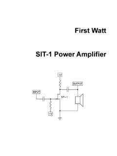
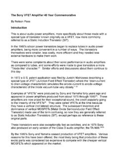
9 The Aleph J used JFET devices for the front end of a two stage single-ended Class A amplifier. The F3 achieved very low distortion using power JFETs in a single-stage, single-ended Class A circuit. The F4 demonstrated that an amplifier did not necessarily require voltage gain to be can follow the progression at is the F5. We want to further push the performance boundaries of simple little amplifiers with a FET two-stage Class A push-pull Quickie Tutorial on FET AmplifiersOne of the aims of these articles is to get people to build amplifiers, so here is some tutorial material to get beginners going. I have written up some of this material before ( The A75 , Audio Amateur 4/1992), but that was 15 years ago, and maybe it will be helpful to repeat bits of it. All 31 years worth can be found at and related links. I m assuming that you understand the concepts of voltage, current, and resistance. If you already know how a FET works, you can skip 1 shows an N channel FET, a quantum mechanical black box with three connections.
10 This device is meant to function as a valve, a little bit like a water faucet. In this picture, the Drain (D) of the FET is attached to an electrical power supply, analogous to the pressurized water supply on the other side of the faucet. You can imagine the pipe as wire, and the tank of water as a battery or even a charged-up continue the metaphor, the voltage of the supply is the water pressure, and the water flowing from the supply is the electrical current. The Source (S) connection of the FET is the output of the faucet. The Gate (G) of the FET is the control pin, and like the handle on the faucet, it controls the amount of electrical current through the FET from the Drain to the Source. For the FET, this control is a function of the relative voltage between the Gate and Source pins. For an N channel FET, raising the Gate positively with respect to Source increases the current , I know some of you are thinking that maybe the Source should be on top and the Drain on the bottom, but they re not.