Transcription of Fisher 1061 Pneumatic Piston Rotary Actuator with …
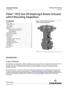
1 1061 pneumatic piston rotary actuator with Style H & J mounting of of Actuator 1. Fisher 1061 ActuatorW4142W4257 1H mounting AdaptationJ mounting Adaptationand Fisher 3610JP PositionerIntroductionScope of ManualThis instruction manual includes installation, adjustment, maintenance, and parts ordering information for the Fisher1061 Pneumatic Piston Rotary Actuator (sizes 30, 40, 60, and 68) with H and J mounting adaptations (see figure 1).Instructions for the positioner, accessories, and, if used, the auxiliary handwheel Actuator are covered in separateinstruction not install, operate, or maintain a 1061 Actuator without being fully trained and qualified in valve, Actuator , andaccessory installation, operation, and maintenance. To avoid personal injury or property damage, it is important tocarefully read, understand, and follow all the contents of this manual, including all safety cautions and warnings. If youhave any questions about these instructions, contact your Emerson sales office or Local Business Partner ManualD100325X0121061 H & J ActuatorJune 2017 Instruction ManualD100325X0121061 H & J ActuatorJune 20172 Table 1.
2 SpecificationsAvailable ConfigurationDouble acting Pneumatic Piston Rotary Actuator forJthrottling service when used with positioner orJon off service when used with switching adaptations include JH mounting forrotary actuation of equipment other than Fishervalves or JJ mounting for Rotary actuation of Fisherkeyed shaft butterfly valves and other keyed shaftequipmentActuator SizesJ30, J40, J60, and J68 Cylinder Operating PressureMinimum bar (20 psig) without positioner or bar (5psig) above Actuator requirement with positioner(1)Maximum Allowable:Sizes 30 and 40: bar (150 psig)Size 60: bar (100 psig)Size 68: bar (85 psig)Torque LimitsLimited by maximum cylinder operating pressure orby tables 2 and 3, whichever is lessMaximum Valve Shaft RotationJ90 degrees or J60 degrees (travel stop requiredfor 60 degrees rotation)Stroking TimeDependent on Actuator size, degrees of rotation, andpositioner if used. If stroking time is critical, contactyour Emerson sales office or Local Business Temperature Capabilities with StandardElastomers-34 to 82_C (-30 to 180_F)Pressure ConnectionsJ 1/4 NPT internal (Standard)J 1/2 and 3/4 optional on size 68 Travel IndicationGraduated scale and pointer located on actuatorcover at Actuator end of valve shaftMounting PositionsSee figure 4 Approximate WeightsSee table 41.
3 See separate manual for positioner 1061 Actuator is a Pneumatic Piston Rotary Actuator for use with Rotary control valves and other equipment. The Hmounting adaptation permits the Actuator to be used with user provided mounting brackets and couplings for rotaryactuation of equipment other than Fisher valves. The J mounting adaptation permits the Actuator to be used for rotaryactuation of Fisher keyed shaft butterfly valves and other keyed shaft equipment that can mount on the H mounting adaptation includes a flat surface mounting plate that is drilled and tapped for attaching theuser provided bracket. Cap screws for attaching the bracket are provided. H mounting also includes an output shaft( with milled flats) to provide the Rotary output either directly or through a user provided coupling(1). Output shaftdiameters and torque limits are listed in table 2. Dimensional information for the mounting plate and output shaft areshown in figure J mounting adaptation uses the standard butterfly valve mounting bracket and provides an output shaft with anattached coupling for keyed equipment shafts.
4 Coupling sizes and torque limits are listed in table 3. Dimensionalinformation for the mounting yoke and output shaft coupling is shown in figure , the 1061 Actuator can be used for either throttling or on off applications. For auxiliary manual operationof the equipment, a side mounted handwheel Actuator is Actuators with H mounting and a mm (2 inch) output shaft are supplied with acoupling for adaptation to either a or mm (1 3/4 or 2 inch) keyed ManualD100325X0121061 H & J ActuatorJune 20173 SpecificationsSpecifications are shown in table 1 for 1061 actuators. Specifications for a given 1061 Actuator as it originally comesfrom the factory are stamped on a nameplate (key 42, figure 6) attached to the ServicesFor information on available courses for 1061 Style H and J actuators, as well as a variety of other products, contact:Emerson Automation SolutionsEducational Services - RegistrationPhone: 1-641-754-3771 or 1-800-338-8158E-mail: an Actuator and valve are shipped together, the Actuator is normally mounted on the valve.
5 Follow the valveinstructions when installing the control valve in the pipeline. If the Actuator is shipped separately or if it is necessary tomount the Actuator on the valve, perform the procedures presented in the Actuator mounting section. WARNINGTo avoid personal injury, always wear protective gloves, clothing, and eyewear when performing any avoid personal injury or property damage caused by bursting of pressure retaining parts, be certain the serviceconditions do not exceed the limits given in table 1 or on the nameplate. Use pressure limiting or pressure relieving devicesto prevent the cylinder pressure from exceeding the maximum allowable cylinder operating with your process or safety engineer for any additional measures that must be taken to protect against installing into an existing application, also refer to the WARNING at the beginning of the Maintenance section in thisinstruction 2. Output Shaft Diameters and Torque Limits for Actuators with H MountingACTUATORSIZEOUTPUT SHAFT DIAMETERTORQUE LIMIT FOR H 1/81 1/2240468111021204140981540, 60 & 1/81 1/22(1)46812102650414010,68023,4301.
6 Coupling supplied for mating with either or mm (1 3/4 or 2 inch) keyed ManualD100325X0121061 H & J ActuatorJune 20174 Table 3. Acceptable Shaft Diameters and Torque Limits for Actuators with J MountingACTUATORSIZECOUPLING AVAILABILITY BY KEYED SHAFT DIAMETERTORQUE LIMIT FOR J , 60, & 1/41 1/22074681030136018304140911012,000 Table 4. Approximate Actuator WeightsACTUATORSIZEALUMINUM HOUSING CONSTRUCTIONCAST IRON HOUSING CONSTRUCTIONkgPoundskgPounds301839224940 235029636033733986685011056123 Actuator MountingUse the following steps to connect the Actuator to a valve or other equipment. Unless otherwise specified, keynumbers are shown in figure 6. WARNINGP erform the steps in the WARNING at the beginning of the Maintenance an Actuator with an H mounting adaptation and a through mm (7/8 through 1 1/2 inch) output shaft, finddimensions and center of gravity information in figures 2 and 3, and approximate weights in table 4. This information is requiredfor proper fabrication of the user provided bracket and For an Actuator with an H mounting adaptation, attach an appropriate mounting bracket (not provided) to themounting plate (key 23) with the cap screws (key 87).
7 See figure 2 for mounting dimensions on the mounting Consult figure 4 for available mounting styles and positions. The Actuator is normally positioned vertically with thevalve or other equipment in a horizontal the milled flats or the coupling on the end of the Actuator output shaft (key 94) are oriented such that the output shaft cannotaccommodate the operated equipment shaft, refer to the Changing Positions portion of the Changing Actuator mounting procedure describes how the output shaft can be repositioned to accommodate the operated equipment If using an Actuator with a J mounting adaptation, note that the valve shaft coupling (key 97) is furnished with twokeyways lettered A & B as shown in figure 5 (letters C and D on the coupling are not used and can be disregarded).Instruction ManualD100325X0121061 H & J ActuatorJune 20175 Align the appropriate keyway with the keyway in the operated equipment shaft. If using a Fisher butterfly valve,align the appropriate keyway on the coupling with the valve shaft keyway indicated in table 5.
8 Then, install thewoodruff key (key 98) in the shaft keyseat, and slide the coupling onto the shaft. It is helpful to apply a light coat ofgrease to the inside of the coupling before sliding it onto the For an Actuator with a J mounting adaptation, secure the mounting yoke (key 23) to the valve with the cap screws(key 87, not shown). For and mm (1 1/4 and 1 1/2 inch) valve shafts, place two spacers (key 99, notshown) between the mounting yoke and valve or other equipment during this For an Actuator with an H mounting adaptation and a through mm (7/8 through 1 1/2 inch) output shaft,slide the Actuator ( with the user provided mounting bracket attached) into the user provided coupling on theoperated shaft. Then, secure the Actuator to the operated equipment in the desired mounting position withappropriate fasteners, such as mounting cap screws. See figure 2 for output shaft For an Actuator with an H mounting adaptation and a mm (2 inch) output shaft (key 94, figure 7), note thatthe valve shaft coupling (key 97, figure 7) is furnished with two keyways lettered A and B as shown in figure 5(letters C and D on the coupling are not used and can be disregarded).
9 Align the appropriate keyway with thekeyway in the operated equipment shaft. Then, install the woodruff key (key 98, not shown in figure 7) in the shaftkeyseat, and slide the coupling onto the shaft using the appropriate coupling keyway (see table 5 and figure 5). It ishelpful to apply a light coat of grease to the inside of the coupling before sliding it onto the shaft. Secure theactuator (user provided mounting bracket) to the operated equipment in the desired mounting position withappropriate fasteners, such as mounting cap If the 1061 Actuator is equipped with an auxiliary handwheel Actuator , make certain that a cylinder bypass valve(key 68, figure 8) is used to equalize cylinder pressure during handwheel operation. Operating the handwheelactuator by itself against the force of differential cylinder pressures is difficult or even impossible. An installation ofa bypass valve is shown in figure to pneumatically operate the 1061 Actuator while an auxiliary manual Actuator is engaged could damage theactuator shaft.
10 Be certain the manual Actuator is disengaged before pneumatically operating the 1061 Follow the instructions given in the Adjustment section before proceeding to the loading connection portion of 5. Keyway Alignment Information(1)DESIREDACTUATORACTIONDESIR EDSHAFTROTATION,DEGREESACTUATORMOUNTINGP OSITIONCOUPLINGKEYWAYTO USE(3)VALVE SHAFT KEYWAY TO USE FOR FISHTAIL DISK VALVES(2) (SEE FIGURE 6)Clockwise to Close Valve Action(4)Counterclockwise to Close Valve Action(4)Flow Left to Right(4)Flow Right to Left(4)Flow Left to Right(4)Flow Right to Left(4)Push Downto Open(PDTO)60 or 901 BNoseTailTailNose2 ATailNoseNoseTail3 BTailNoseNoseTail4 ANoseTailTailNosePush Downto Close(PDTC)60(5) or 901 ATailNoseTailNose2 BTailNoseTailNose3 ANoseTailNoseTail4 BNoseTailNoseTail1. For actuators with H mounting and mm (2 inch) output shafts, and for actuators with J For conventional disk valves, use either valve shaft See figure 6 for reference coupling orientation to use with this When viewed from Actuator side of For 60 degree rotation with PDTC action, the coupling and Actuator output shaft assembly will be offset 30 degrees clockwise (for Actuator housing construction style B) or counterclockwise(for Actuator housing construction Style A) in the lever when viewed from the splined end of the Actuator shaft.