Example: air traffic controller
Flange Dimensions Based on Tables D and E of BS 10 : 1962
Flange Dimensions Based on Tables D and E of BS 10 : 1962 www.steel-flange.com sales@steel-flange.com British Standard BS 10 : 1962 - Specification for Flanges and Bolting for Pipes, Valves, and Fittings. This covers plain, boss, integrally cast or forged, and welding neck type flanges, in ten tables.
Tags:
Information
Domain:
Source:
Link to this page:
Documents from same domain
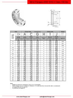
Blind Flanges-ANSI B16.5 Class 150 lbs - Steel Flange
www.steel-flange.comwww.steel-flange.com sales@steel-flange.com Blind Flanges-ANSI B16.5 Class 150 lbs Notes - Weights are based on manufacturer’s data and are approximate.
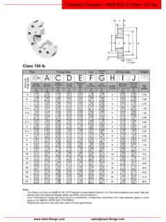
Threaded Flanges - ANSI B16.5 Class 150 lbs - Steel …
www.steel-flange.comwww.steel-flange.com sales@steel-flange.com Threaded Flanges - ANSI B16.5 Class 150 lbs Notes - The thread conforms to ASME B1.20.1 NTP threads as …
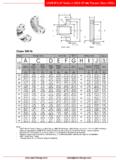
Class 300 lb - Steel Flange
www.steel-flange.comASME B16.47 Series A (MSS SP-44) Flanges Class 300lbs www.steel-flange.com sales@steel-flange.com Notes - ASME B16.47 Series A flanges (> NPS 26) are MMS SP-44 …
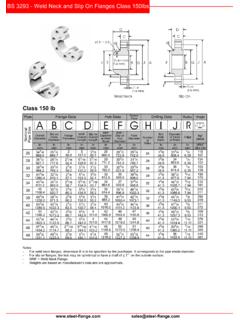
BS 3293 - Weld Neck and Slip On Flanges Class …
www.steel-flange.comBS 3293 - Weld Neck and Slip On Flanges Class 150lbs www.steel-flange.com sales@steel-flange.com Notes - For weld neck flanges, dimension B is to be specified by the purchaser.
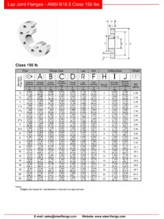
Lap Joint Flanges - ANSI B16.5 Class 150 lbs
www.steel-flange.comLap Joint Flanges - ANSI B16.5 Class 150 lbs E-mail: sales@steelflange.com Website: www.steel-flange.com Notes - Weights are based on …
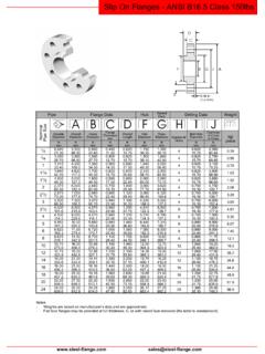
Slip On Flanges - ANSI B16.5 Class 150lbs - Steel …
www.steel-flange.comwww.steel-flange.com sales@steel-flange.com Slip On Flanges - ANSI B16.5 Class 150lbs Notes - Weights are based on manufacturer’s data and are approximate.
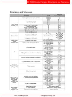
Dimensions and Tolerances - Steel Flange
www.steel-flange.comBS 4504 Circular Flanges - Dimensions and Tolerances www.steel-flange.com sales@steel-flange.com Dimensions and Tolerances
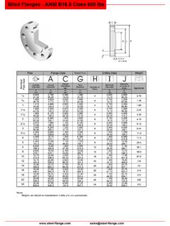
ANSI B16.5 Class 600 lbs - Steel Flange
www.steel-flange.comwww.steel-flange.com sales@steel-flange.com Notes - Weights are based on manufacturer’s data and are approximate.
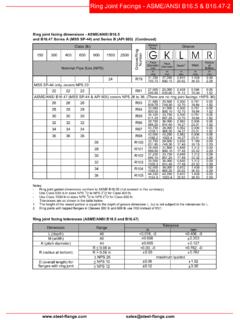
Ring Joint Facings - ASME/ANSI B16.5 & B16.47-2
www.steel-flange.comRing Joint Facings - ASME/ANSI B16.5 & B16.47-2 www.steel-flange.com sales@steel-flange.com Notes - Ring joint gasket dimensions conform to ASME B16.20 (not covered in this summary).
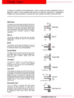
Flange Types
www.steel-flange.comwww.steel-flange.com sales@steel-flange.com Flange Types A Flange is a method of connecting pipes, valves, pumps and other equipment to form a
Related documents
![STEEL FLANGE DIMENSIONS t;:;F~ m t+--G;:]](/cache/preview/7/4/2/8/1/a/1/4/thumb-74281a14278b9db3ad776ab389c7d134.jpg)
STEEL FLANGE DIMENSIONS t;:;F~ m t+--G;:]
www.wosupply.comNominal Flange Companion Valve Diameter of Diameter of Diameter of Number Diameter Stud Bolts Machine Pipe Diameter Flange Flange Raised Face Bolt Circle Bolt Holes of of with 2 Nuts Bolts Size A B B c D E Bolts F G '12 3'12 7/ts 1:VS 2:VS % 4 …
Dimensions, Sizes and Specification of DIN Flange & DIN ...
gttrade.byDIN 254 SLI4 -P ON FLANGE S DIN 252 BLIN7 FLANGED S DIN 263 WELDIN4 NECG FLANGEK S SEE DIN 2559 d2 d2 I. d4 - • K0-D .— d3-— K0 > - D « SLIP-ON/PLATE ^TTT WELDING NECK BLIND Unit:mm Bore Common Dimension Hub Raised Face Drilling Approx.Weight(kg) Nomi-nal Bore d 1 Void-ing Neck Slip -on Blind d 3 d 4 Nomi- Dia. nal of of …
NORME EUROPÉENNE 1092-1 EN DAAD STAN EUROPEAN
www.htcflange.coma) Designation. eg. flange. lapped end or collar: b) Number of this standard. EN 1092-1: c) Number of flange type in accordance with figures 1 and 2: d) Type of flange facing in accordance with figure 3: e) DN (nominal size): f3 PN designation:

connections Workable Flange Gages - AISC
www.aisc.org8 in.) column flange with an extended end-plate moment con-nection. The bolts used are 7⁄ 8-in. diameter A325–N (D = 1.535 in.). The minimum gage for the W14x550 column is 61/4 in., however per the requirements for extended end-plate moment connec-tions, the maximum gage should be equal to the flange width of
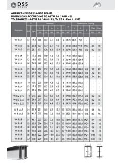
AMERICAN WIDE FLANGE BEAMS DIMENSIONS …
www.dsssteel.comAMERICAN WIDE FLANGE BEAMS DIMENSIONS ACCORDING TO ASTM A6 / A6M - 03 TOLERANCES : ASTM A6 / A6M - 03 Designation lbs/ft kg/m G A mm h h t w h i d Pmix Dimensions Dimensions for Detailing t f r Pmax mm mm mm mm mm mm Ø mm² mm mm W 10 x 4 W 10 x 4 W 10 x 4 W 10 x 4 W 10 x 5.75 W 10 x 5.75 W 10 x 5.75 W 10 x 5.75 W 10 x 8 W 10 …

SAE PUMP AND MOTOR MOUNTING FLANGE AND SHAFT …
www.hydraulicsupermarket.comSpline Details . Nominal DIA (ND) Total Length (TL) AA : 9T 20/40 DP . 0.500 : 1.062 . A : 9T 16/32 DP . 0.625 : 1.250 . AH : 11T 16/32 DP . 0.750 : 1.490 . B : 13T ...
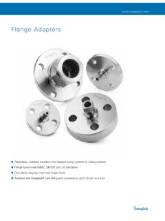
Flange Adapters (MS-02-200;rev J;en-US;Catalog)
www.swagelok.comFlange Adapters 1 FLANGE ... D H A E J B F, flat Pressure-Temperature Ratings Ratings are taken from ASME B16.5, Table 2-2.2 and Table II-2-2.2 (based on A182 316 stainless steel material). Pressure ratings for fittings with a flange end connection and another end connection are determined by the connection with the

FLANGE BOLTING GUIDE
cca54520de545be69264-cd6844ebeaebf35ce76089ee04af4af7.r83.cf2.rackcdn.comA Division of Bray International, Inc. The Ultimate Critical Service Triple Offset Valve Flange Bolting Guide All information herein is proprietary and confidential and may not be copied or reproduced without the expressed written consent of BRAY INTERNATIONAL, Inc.

FLANGE DIMENSIONS - DIN
www.shipserv.comD = Flange diameter n = Number of bolt holes Hcd = Hole circle diameter d = Diameter of bolt holes L1 = Face to Face Length L1 = Face to Center Length L2 = Face to Center Length In order to supply correct valve we want information about dimensions acc to below. If possible also medium, pressure and temperature.