Transcription of Flex Crack Mitigation - KEMET
1 As part of continuous process improvement at KEMET ,most failure modes caused by the capacitor manufacturingprocess have been systematically eliminated. Today thesecapacitor manufacturing-related defects are now at a parts-per-billion (PPB) level. Pareto analysis of customer com-plaints indicates that the #1 failure mode is IR failure due toflex CracksFlex cracks have been known in PCB manufacturing forquite some time. flex cracks are created in capacitorswhen board flex stress / bending stress is applied to a circuitboard with ceramic components already affixed to the the ceramic capacitor is inherently hard, non-elastic, andbrittle (relative to the PCB), any bending of the board cre-ates stress, and that stress can be transmitted through thesolder joint, directly to the ceramic body.
2 This stress mustbe relieved somehow and this stress relief can result in thecreation of a board flex Crack (See Figure 1). Figure 1. Typical flex CrackIn PCB assembly, some of the sources of this stressinclude the following: Connector Assembly/Connector Use MLCC splaced close to connectors are particularly susceptibleto board flex stress (See Figure 2). Depanelization where many small boards areassembled as one large panel that must then be sep-arated, especially when MLCC s are located close tothe edge of the PCB (See Figure 3).Figure 2. Filter capacitor very near to thru-hole 3. Board singulation can flex stressceramic capacitors near board edge. Box build assembly of a final product can involvestresses as boards are fitted together particularlygiven the demands for today s thinner product offer-ings.
3 Figure 4. Parts located near connectors can be susceptible to board flex Crack Mitigationby Bill Sloka, Ceramic Technical Consultant KEMET Electronics Corporation Box 5928 Greenville, SC 29606 (864) 963-6300 2008 PCB assembly continues to evolve, and by carefullyunderstanding and controlling the board assembly process,the occurrence of board flex stress can be , these board flex stresses have not been eliminat-ed and in many cases the worst-case scenario is a result-ant short circuit which leads to field failure. KEMET nowoffers a portfolio of engineered solutions to mitigate theeffects of board flex stress. By creating solutions that lendthemselves to open failure mode rather than short circuitfailure mode, KEMET is offering a measure of protection forcustomers who know that short circuit failure is not anoption.
4 FAQ s and DefinitionsThe following statements are based on extensive industryresearch, whitepapers, and presentations. All of thesequestions are answered assuming the customer is using astandard, 2-terminal Does a flex Crack always lead to failure?Answer no; as with all cracks in MLCC s, there needs to besome type of ionic penetration or humidity along thecrack path which allows current to flow betweenelectrode plates of opposite polarity, in order for thechip to fail. (See Figure 5).Figure 5. Yellow electrode represents (+); blue electrode represents (-); flex Crack leads to Does it matter which direction the board is flexed?Answer no; our studies have shown that a boardbent up or down leads to the formation of a boardflex Crack that looks the same regardless of boardbend direction, all other factors being Does a flex Crack always have the same Crack sig-nature?
5 Answer yes. There is a distinctive cracksignature for board flex cracks it always startsnear the edge of the termination margin, and usual-ly extends upwards toward the termination flex Crack signature is distinctly different thanother Crack signatures in MLCC s. (See Figure 6)Figure 6. Red Crack represents flex Crack ; greencrack represents typical thermal shock Crack ; blue Crack represents mechanical Are there PCB assembly process parameters thatcan be modified to reduce the risk of board flexcracks?Answer yes. Studies have shown that by minimizing the amount of solder (size of solder fil-let), and minimizing chip size (smaller chips areinherently more robust than larger chips), thechances of failure due to board flex cracking can Are there ways to place parts away from problem areas on the PCB?
6 Answer yes. By placing partsparallel to the edge of the PCB, as far away from theedge of the PCB as practical, and as far away fromthru-hole connectors/screws/etc., manufacturerscan reduce their risk of MLCC board flex Does KEMET ever ship capacitors with flex cracks,while still in the tape & reel?Answer no, flexcracks can only occur post solder flex Crack Solutions at KEMETIf board flex stress cannot be eliminated, there are sev-eral options available that offer methods to mitigate the riskassociated with board flex cracks. In order to offer a cost-effective solution, there are several options available, basedon the capacitance value selected. For lowcapacitance values, KEMET offers theFloating Electrode (FE-CAP) design. This is alsoknown in the industry as a Serial Cap design, as theFloating Electrode part contains two parts in series,within a singular capacitor body.
7 In Automotive(Clamp 30) designs, sometimes 2 distinct capacitors will be used in series on the PCB the FE-CAP givesa designer this two parts in series - within a singularcapacitor. This solution works by eliminating theshort-circuit path between electrodes of oppositepolarity (See Figure 7). Due to the sacrifice of activeFigure 7. flex Crack does not complete circuit - noshort circuit necessitated by the creation of two serial capaci-tors, the Floating Electrode solution can only be usedfor lower capacitance values. To order this device,simply place an S for Serial Cap in the 6thdigit of theKEMET part number. For customers desiring an additional mode of pro-tection, KEMET now offers the FF-CAP (FloatingElectrode + Flexible Termination see FlexibleTermination description later in this paper).
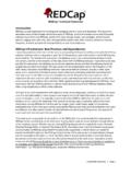
8 Toorder this device, place a Y in the 6thdigit of theKEMET part number. KEMET Electronics Corporation Box 5928 Greenville, SC 29606 (864) 963-6300 For midcapacitance values, KEMET offers theOpen Mode solution. The Open Mode device cre-ates a safe zone on both ends of the capacitor (SeeFigure 8), so that only the innermost portion of thecapacitor is active area. Any board flex Crack that occurs (remember, this Crack always starts within theend termination) can only cross electrodes of likepolarity; thus eliminating the possibility of a short-cir-cuit failure from a board flex Crack . As with the FE-CAP, active area has been sacrificed in order to cre-ate the safe zones on both ends of the chip; thus,the Open Mode solution is only applicable for midcapacitance values.
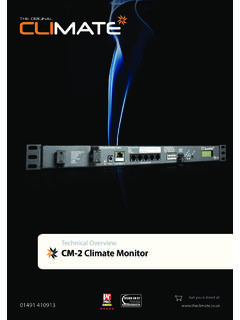
9 To order this device, place an F for Fail Open in the 6thdigit of the KEMET partnumber. Open Mode can be ordered with FlexibleTermination by changing the 6th digit of the KEMETPart Number to a D .Figure 8. Blue represents (-), Yellow represents (+), flex Crack only crosses electrode of like polarity. Finally, for highcapacitance values (also called HiCVin the industry), KEMET offers the Flexible Termi-nation (FT-CAP). KEMET applies a special conduc-tive silver epoxy on both end terminations, betweenthe copper/electrode interface and the nickel/tin plat-ing. This special epoxy layer is essentially a tear-away solution, providing a path of least resistancefor board flex stress. This solution acts to steer thepotential flex Crack away from the ceramic body, intothe more benign area of the termination (See Figure9).
10 Technically, Flexible Termination can be applied toany commercial SMD (Surface Mount) product, butdue to additional manufacturing costs (primarily mate-rials and labor), the Flexible Termination ismore cost effective when used on HiCV s Flexible Termination offers up to 5mm ofboard bend stress capability. To order this device,place an X for Flexible Termination in the 6thdigit ofthe KEMET part 9. Flexible termination moves flex cracks to the end termination, away from the ceramic solutions mentioned above are available today fromKEMET. As Automotive is a primary market focus for theseFlex Crack solutions, KEMET has qualified all of the solu-tions per AEC-Q200 (documentation available uponrequest). For more specific information, including availablecapacitance values, sample requests, datasheets, etc.