Transcription of Flow Configuration - membranes.com
1 Page 1 of 8 01/23/01 Flow Configuration There are several flow configurations for RO that allow the user to get the most out of the system. This paper will cover a few of the techniques used in RO design to optimize system performance. These techniques include the use of concentrate staging and concentrate recirculation to increase recovery, permeate staging to attain ultrapure standards of separation, and permate throttling and interstage boosting to manipulate the flow distribution between stages. SYSTEM COMPONENTS RO systems consist of the following basic components: Feed water supply unit Pretreatment system High pressure pumping unit Membrane element assembly unit Instrumentation and control system Permeate treatment and storage unit Cleaning unit The membrane assembly unit (RO block) consists of a stand supporting the pressure vessels, interconnecting piping, and feed, permeate and concentrate manifolds.
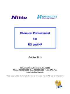
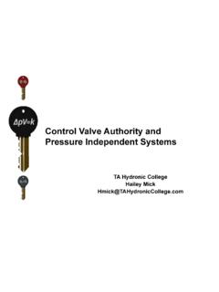
2 Membrane elements are installed in the pressure vessels. The pressure vessel has permeate ports on each end, located in center of the end plate, and feed and concentrate ports, located on the opposite ends of the vessel. Each pressure vessel may contain from one to seven membrane elements connected in series. Page 2 of 8 01/23/01 As shown above, the permeate tube of the first and the last element is connected to the end plates of the pressure vessel. Permeate tubes of elements in the pressure vessel are connected to each other using interconnectors. On one side of each membrane element there is a brine seal, which closes the passage between outside rim of the element and inside wall of the pressure vessel. This seal prevents feed water from bypassing the membrane module, and forces it to flow through the feed channels of the element. As feed water flows through each subsequent membrane element, part of the feed volume is removed as permeate.
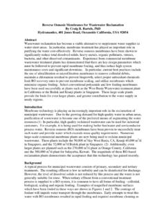
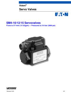
3 The salt concentration of the remaining feed water increases along the pressure vessel. Permeate tubes conduct the permeate from all connected elements. The collected permeate has the lowest salinity at the feed end of the pressure vessel, and increases gradually in the direction of the concentrate flow. CONCENTRATE STAGING and PYRAMID DESIGN A system is divided into groups of pressure vessels, called concentrate stages. In each stage pressure vessels are connected in parallel, with respect to the direction of the feed/concentrate flow. The number of pressure vessels in each subsequent stage decreases in the direction of the feed flow, usually in the ratio of 2:1, as shown below. Brine sealMembraneelementPermeate portFeed portInterconnectorConcen-trate portMembraneelementMembraneelementPressu re vesselEnd platePressure vessel with three membrane elements Page 3 of 8 01/23/01 Flow diagram of a two stage RO systemPGPGP ressure vessel,1st stagePressure vessel,1st stagePressure vessel,1st stagePressure vessel,1st stagePressure vessel,2nd stagePressure vessel,2nd stageConcentrateFeedPermeate Thus, one can visualise that the flow of feed water through the pressure vessels of a system resembles a pyramid structure: a high volume of feed water flows in at the base of pyramid, and a relatively small volume of concentrate leaves at the top.
4 The decreasing number of parallel pressure vessels from stage to stage compensates for the decreasing volume of feed flow, which is continuously being partially converted to permeate. The permeate of all pressure vessels in each stage, is combined together into a common permeate manifold. The objective of the taper Configuration of pressure vessels is to maintain a similar feed/concentrate flow rate per vessel through the length of the system and to maintain feed/concentrate flow within the limits specified for a given type of membrane element. Very high flow through a pressure vessel will result in a high pressure drop and possible structural damage of the element. Very low flow will not provide sufficient turbulence, and may result in excessive salt concentration at the membrane surface. For a given RO unit, the number of concentrate stages will depend on the permeate recovery ratio and the number of membrane elements per pressure vessel.
5 In order to avoid excessive concentration polarization at the membrane surface, the recovery rate per individual membrane element should not exceed 18%. It is common engineering practice to design brackish RO systems so that the average recovery rate per 40 inch long membrane element will be about 9%. Accordingly, the number of Page 4 of 8 01/23/01 concentrate stages for an RO unit having 6 elements per pressure vessel would be two for recovery rates over 60%, and three for recovery rates over 75%. With pressure vessels containing seven elements, a two stage Configuration would be sufficient for recovery rates up to 85%. CONCENTRATE RECIRCULATION The simplest membrane element assembly consists of one pressure vessel, containing one membrane element. Such a Configuration , used in a very small systems, can operate at a limited permeate recovery ratio, usually about 15%.
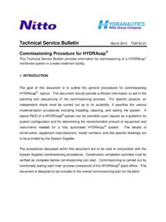
6 In order to increase the overall system recovery ratio and still maintain an acceptable concentrate flow, a part of the concentrate stream is returned to the suction of the high pressure pump. The concentrate recycling Configuration , shown below, is used mainly in a very small RO units. An advantage of such a design is the compact size of the RO unit. The disadvantage of concentrate recirculation design is related to the need for a larger feed pump to handle higher feed flow. Accordingly, the power consumption is relatively higher than that required in a multistage Configuration . Due to blending of the feed with the concentrate stream, the average feed salinity is increased. Therefore, both the feed pressure and the permeate salinity are higher as well. Flow diagram of a single stage RO unit with concentrate recirculationPGPG Page 5 of 8 01/23/01 CONCENTRATE STAGING A commercial RO unit usually consists of single pump and a multistage array of pressure vessels.
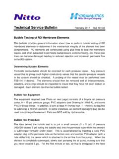
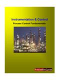
7 A simplified block diagram of a two stage RO unit is shown on the next page. The concentrate from the first stage becomes the feed to the second stage; this is what is meant by the term "concentrate staging." The flows and pressures in the multistage unit are controlled with the feed and concentrate valves. The feed valve, after the high pressure pump, controls feed flow to the unit. The concentrate valve, at the outlet of RO block, controls the feed pressure. Flow diagram of a two stage RO systemPGPGPG204 bar179 bar154 bar200 m3/hr112 m3/hr150 m3/hr38 m3 m3/hr FLOW DISTRIBUTION In some cases it is necessary to equilibrate permeate flow between stages decrease permeate flow from the first stage and increase permeate flow from the last stage. This can be accomplished in one of two design configurations. One solution is to install a valve on the permeate line from the first stage, as shown.
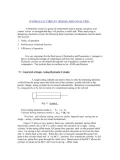
8 Page 6 of 8 01/23/01 By throttling this valve, permeate back pressure will increase, reducing net driving pressure and reducing permeate flux from the first stage. The differential permeate flux is produced from the second stage by operating the RO unit at a higher feed pressure. Flow diagram of a two stage RO system with permeate throttlingPGPGPG236 bar50 bar182 bar200 m3/hr101 gpm34 m3/hr49 m3 m3/hrPG210 bar The other solution is to install a booster pump on the concentrate line between the first and the second stage, as diagrammed below. The booster pump will increase feed pressure to the second stage resulting in higher permeate flow. The advantage of the permeate throttling design is simplicity of the RO unit and low capital cost. However, this design results in additional power losses due to permeate throttling and higher power consumption.
9 The interstage pump design requires modification of the interstage manifold and an additional pumping unit. The investment cost is higher than in the first design, but the power consumption is lower. Page 7 of 8 01/23/01 Flow diagram of a two stage RO system with interstage pumpPGPGPG186 bar160 bar182 bar200 m3/hr150 m3/hr49 m3 m3/hr210 barPG PERMEATE STAGING For some applications, the single pass RO system may not be capable of producing permeate water of a required salinity. Such conditions may be encountered in two types of RO applications: Seawater RO systems, which operate on a very high salinity feed water, at high recovery ratio and/or at high feed water temperature. Brackish RO applications which require very low salinity permeate such supply of makeup water for pressure boilers or production of rinse water for microelectronics applications.
10 To achieve an additional reduction in permeate salinity, the permeate water produced in the first pass is desalted again in a second RO system. This Configuration is called a two pass design, or "permeate staging." Depending on quality requirements, all or part of the first pass permeate volume is desalted again in the second pass system. The system Configuration is known as a complete or partial two pass system depending on whether all of the permeate is fed to the second pass or not. Page 8 of 8 01/23/01 The first pass permeate is a very clean water. It contains very low concentrations of suspended particles and dissolved salts; therefore, it does not require any significant pretreatment. The second pass system can operate at a relatively high average permeate flux and high recovery rate. The common design parameters for the second pass RO unit are average flux rate of 20 gfd and recovery rate of 85% - 90%.