Transcription of Flow Cytometry Basics Guide - Bio-Rad
1 Flow CytometryPractical Advice to Get You Started in FlowFlow Cytometry Basics GuideVisit for more information Flow Cytometry Basics Guide | 1 Table of ContentsChapter 1 Principles of the Flow CytometerFluidics System ..3 Optics and Detection ..4 Signal and Pulse Processing ..6 Electrostatic Cell Sorting ..9 Chapter 2 Principles of FluorescenceFluorophores and Light ..11 Fluorescence ..12 Why Use a Fluorescent Marker? ..13 Which Fluorophores are Useful for Flow Cytometry ? ..13 Single and Tandem Dyes ..14 Fluorescent Proteins ..14 Fluorescence Compensation ..16 Compensation Controls ..18 Chapter 3 Data AnalysisGates and Regions ..19 Single-Parameter or Univariate Histograms ..21 Two-Parameter or Bivariate Histograms ..22 Backgating to Confirm Gating Strategies ..24 Chapter 4 Controls in Flow cytometryUnstained Controls ..25 Isotype Controls ..26 Single Staining and Compensation Controls.
2 27 Fc Blocking Controls ..28 Fluorescence Minus One Controls ..29 Intracellular Staining Controls ..30 Biological Controls ..30 Chapter 5 Optimizing your ExperimentsSample Preparation ..31 Live/Dead Exclusion ..32 Autofluorescence ..34 Doublet Discrimination .. 34 Collect a Statistically Relevant Number of Cells ..35 Permeabilization and Fixation for Intracellular Antigens ..36 2 | Flow Cytometry Basics Guide Chapter 6 Multicolor Panel BuildingResolution of Signal ..37 Instrument Configuration ..38 Fluorophore Separation ..38 Antigen Density ..38 Fluorophore Properties ..38 Marker Expression Patterns ..39 Dump Channels ..39 Antibody Titration ..39 Panel Building Tools ..40 Chapter 7 Common Applications and New TechnologyImmunophenotyping ..41 Apoptosis ..42 Proliferation and Cell Cycle ..43 Signaling and Phosphoflow ..44 Small Particle Detection ..44 Gene Expression and Transfection.
3 44 Absolute Quantification ..45 Particle Internalization ..45 Fluorescence in situ Hybridization and RNA Detection ..45 Innovations in Flow Cytometry ..45 Recommended Reading ..46 Chapter 8 Common ProtocolsSample Preparation ..47 Preparation of Cells for Flow Cytometry ..48 Preparation of Tissue Culture Cells Stored in Liquid Nitrogen ..49 Preparation of Tissue Culture Cells in Suspension ..49 Preparation of Adherent Tissue Culture Cell Lines ..50 Preparation of Human Peripheral Blood Mononuclear Cells ..51 Preparation of Peritoneal Macrophages, Bone Marrow, Thymus, and Spleen Cells ..51 Direct Immunofluorescence Staining of Surface Epitopes of Cells and Blood ..52 Indirect Immunofluorescence Staining of Surface Epitopes of Cells and Blood .. 53 Direct Staining of Intracellular Antigens and Cytokines: Leucoperm Accessory Reagent Method.
4 54 Direct Immunofluorescence Staining of Intracellular Antigens: Methanol plus Leucoperm Method ..56 Direct Immunofluorescence Staining of Intracellular Cytokines in Blood ..57 Propidium Iodide Staining of Cells for Cell Cycle Analysis ..60 BrdU Staining of Cells for Cell Cycle Analysis and Apoptosis ..61 Chapter 9 Troubleshooting Troubleshooting Guide ..63 Glossary ..65 Principles of the Flow CytometerFlow Cytometry Basics Guide | 31 Principles of the Flow Cytometer Fluidics SystemOne of the fundamentals of flow Cytometry is the ability to measure the properties of individual particles . When a sample enters a flow cytometer, the particles are randomly distributed in the 3-D space of the sample line, the diameter of which is significantly larger than the diameter of most cells . The sample must therefore be ordered into a stream of single particles that can be interrogated individually by the instrument s detection system.
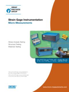
5 This process is managed by the fluidics system .The fluidics system consists of a central core through which the sample fluid is injected, enclosed by an outer sheath fluid . Due to narrowing of the sheath (in a nozzle or cuvette) the fluid velocity is increased . The sample is introduced into the center and is focused by the Bernoulli effect (Figure 1) . This allows the creation of a stream of particles in single file and is called hydrodynamic focusing . Under optimal conditions (laminar flow) there is no mixing of the central fluid stream and the sheath fluid . Fig. 1. Hydrodynamic focusing produces a single stream of particles. Without hydrodynamic focusing, the cuvette (typically 250 x 250 m or 180 x 480 m) or nozzle of the instrument (typically 70-130 m) would not create a focused stream of cells and analysis of single cells would not be possible . With hydrodynamic focusing the cells flow in single file through the illumination source, called the interrogation point, allowing single cell analysis.
6 Hydrodynamic focusing regionSheath fluidCells in single file4 | Flow Cytometry Basics Guide Principles of the Flow Cytometer Optics and DetectionAfter hydrodynamic focusing, each particle passes through one or more beams of focused light . Light scattering or fluorescence emission (from autofluorescence or if the particle is labeled with a fluorophore) provides information about the particle s properties . Lasers are the most commonly used light sources in flow Cytometry .Lasers produce a single wavelength of light (a laser line) at a specific frequency . They are available at different wavelengths ranging from ultraviolet to far red and have a variable range of power levels (photon output/time typically specified in mW) .Light that is scattered in the forward direction after interacting with a particle, typically up to 20o offset from the laser beam's axis, is collected by a photomultiplier tube (PMT) or photodiode and is known as the forward scatter (FSC) channel.
7 This angle can however vary depending on your instrument, leading to variation of FSC signals between different machines . This FSC measurement can give an estimation of a particle's size with larger particles refracting more light than smaller particles, but this can depend on several factors such as the sample, the wavelength of the laser, the collection angle and the refractive index of the sample and sheath fluid . A good example of this is in the detection of small particles . When the particles are smaller than the wavelength of the illumination source, e .g . a 200 nm exosome passing through a 488 nm laser, does not necessarily scatter light in a forward direction .Light measured at a 90o angle to the excitation line is called side scatter (SSC) . The SSC can provide information about the relative complexity (for example, granularity and internal structures) of a cell or particle; however as with forward scatter this can depend on various factors.
8 Both FSC and SSC are unique for every particle and a combination of the two may be used to roughly differentiate cell types in a heterogeneous population such as blood . However, this depends on the sample type and the quality of sample preparation, so fluorescent labeling is generally required to obtain more detailed information .Fluorescence measurements taken at different wavelengths can provide quantitative and qualitative data about fluorophore-labeled cell surface receptors or intracellular molecules such as DNA and cytokines . Most flow cytometers use separate channels and detectors to detect emitted light, the number of which vary according to the instrument and the manufacturer . Detectors are either photomultiplier tubes or avalanche photodiodes (APD) . PMTs are the most commonly used detectors .The specificity of detection is controlled by optical filters, which block certain wavelengths whilst transmitting (passing) others.
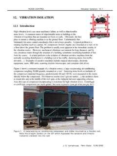
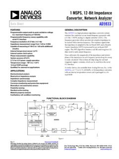
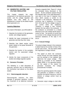
9 There are three major filter types . Long pass filters allow light through above a cutoff wavelength; short pass filters permit light below a certain wavelength and band pass filters transmit light within a specified narrow range of wavelengths (termed a band width) . These dichroic filters can block light by phased reflection allowing certain light to pass through and interfering with other wavelengths (Figure 2) .Flow Cytometry Basics Guide | 5 Principles of the Flow CytometerFig. 2. Different types of optical dichroic filter is also a mirror when placed at an angle to the oncoming light . This type of filter can now perform two functions . First, it allows specific wavelengths to pass in the forward direction, second it can reflect light at a 90o angle . This allows the light path to be passed through a series of filters . The precise choice and order of the filters can be arranged so that multiple signals can be detected simultaneously (Figure 3).
10 Light sourceLight sourceLight source<540 nm light transmitted620 640 nm light transmitted<575 nm light transmitted>520 nm light transmitted575 nm Short Pass Filter520 nm Long Pass Filter630/20 nm Band Pass FilterLight source>540 nm light reflected540 nm Dichroic Short Pass Mirror6 | Flow Cytometry Basics Guide Principles of the Flow Cytometer Fig. 3. Schematic overview of a typical flow cytometer setup. FL, fluorescence; PMT, photomultiplier tube; SSC, side scatter; FSC, forward scatter; blue arrow, light path .Signal and Pulse ProcessingAny time a particle passes through the interrogation point and generates a signal a pulse is generated in every detector . These pulses reflect the passage of the particle through the laser beam or beams and the signal generated at each point in the cell s path . These pulses can be mapped by plotting signal as a function of time .As the particle enters the laser beam spot, it will generate scattered light and fluorescence signals, which will ultimately manifest in a stream of electrons (current) from the anode of the PMT.