Transcription of FMCW Radar System - University of Waterloo
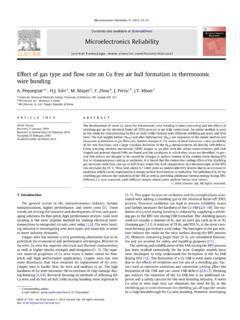
1 FMCW Radar SystemMostafa AlizadehJul 09, 2019 PRELIMINARY ON USING MMWAVE RADARS1 Brief introduction to TI radar32 FMCW Radar Radar basics .. equation .. detection .. or speed detection .. of arrival detection .. spectral estimation .. detection with CFAR ..113 Radar ..134 Notes on parallel processing155 How to use Radar .. detection ..176 Radar module .. UPDATES: .. module ..247 Application contents ..258 Error handling279 Processing module ..2910 Example of using Radar API3311 Glossaries3512 Copyright3713 Indices and tables39iPython Module Index41iiFMCW Radar SystemThe Radar application is in the suppport ofsensorcommunity to expedite developement stages of sensing application is developed based on TI radars forreal-timeprocessing and ON USING MMWAVE RADARS1 FMCW Radar System2 PRELIMINARY ON USING MMWAVE RADARSCHAPTERONEBRIEF INTRODUCTION TO TI RADARHere you should explain the main features of the TI Radar .
2 3 FMCW Radar System4 Chapter 1. Brief introduction to TI radarCHAPTERTWOFMCW Radar INTRODUCTIONTI mmwave radars arefrequency modulated continuous wave(FMCW) radars such that the frequency is swept radars have unique advantages, which cannot be presented in other radars at once. Those are: Being a mm-wave Radar : the high attenuation in mmwave frequencies provides a high isolation between theco-located operating radars even if they are separated in a few meters. Indeed, tiny displacements in mm arecomparable to the wavelength thus they can be detected. This high sensitivity is required to detect the chest wallmovement, which is in mm order. Discriminating range or localizing: because the Radar can distinguish the reflections from different ranges,potentially it can be used for multi-subject vital signs detection.
3 This feature is recognized as the main advantageof an FMCW Radar in1. Indeed, high propagation attenuation reduces the possibility of having an echo signal,which is bounced off multiple reflectors. Most probably, the echo signal is reflected off a single object if theenvironment is not rich scattering. In that area, the received signal at particular range experienced a line of sightwireless channel. In contrast, CW radars suffer from multipath fading because they collect all reflections fromall objects at all visible ranges in a one sinusoid signal. Being robust against thermal noise: FM signals are more robust against noise in comparison to AM , in FMCW radars the vital sign information is encoded in the received phase similar to FM signals.
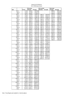
4 Thus,FMCW Radar is less affected by the noise in comparison to impulse FMCW Radar basicsIn any Radar , the electromagnetic wave is sent into the environment containing various objects. Then the echo of thewave is captured at a receiver. A simplified block diagram of such a System is shown inFig. 1in which both thetransmitter and the receiver are at the same location. Each chirp at the output of the FMCW generator is a sinusoidsignal whose frequency is swept from fmin to fmax (Fig. 2). Here the frequency is swept linearly with a positive slopeof K and a duration of implying that the sweeping bandwidth is = . The received signal at theoutput port of the receiver antenna is amplified and correlated with the transmit signal, which results in a signal calledbeat signal.
5 The beat signal contains information about the objects in the scene. Particularly, the delay in the reflectedsignal is translated to an instantaneous frequency difference between the transmitted and the received Wang, A. Pohl, T. Jaeschke, M. Czaplik, M. K ny, S. Leonhardt, and N. Pohl, A novel ultra-wideband 80 ghz fmcw Radar System forcontactless monitoring of vital signs, in 2015 37th Annual International Conference of the IEEE Engineering in Medicine and Biology Society(EMBC), Aug 2015, pp. 4978 Radar SystemFig. 1 Fig. 2 Assume that the complex chirp signal is: ( ) = exp( (2 + 2)) ,0< < (1) is the start frequency (and is the corresponding wavelength) and At is the magnitude related to the transmitpower.
6 Suppose that there is only a single small object situated at the distance of R0 to the Radar but it is moving aroundR0, which results in a time-varying distance to the Radar . Let us denote this time-varying distance by ( ) = 0+ ( )and x(t) is a function represents the distance variations around R0. Furthermore, the reflected wave off the object atthe receiver is the delayed version of s(t) with a delay of = 2 ( )/ , which is the round-trip time of the wave. c isthe light speed throughout the whole paper. Consequently, the IF signal for only a single chirp duration will be: ( ) = ( ) *( )= exp ( ( ( ) ( ))), < < ,(2)The thermal noise and other channel considerations are ignored for simplifications, but has a relationship to by6 Chapter 2.
7 FMCW Radar introductionFMCW Radar Systemthe Radar equation2. The beat signal, ( ), can be expressed as follows: ( ) = exp( (2 + 2 2 )) exp ( (2 + 2 )= exp ( ( ( ) + )), < < ( ) exp ( ( ( ) + )), < < (3) ( ) = 4 0+ ( ) , = 4 0 ,(4)the second approximate equality ineq3is obtained by ignoring the third term in the phase, which is very small. Thethird term is negligible because K is in1012 / order while is in 1ns thus the term is in the order of10 (eq4) obtained after replacing to (eq3) and ignoring the ( ) term because t is in1 and x(t) is almostconstant for one chirp as we will see later. Furthermore, ( )varies with x(t) relative to.)
8 So, the phase variationsin the scale of the maximum wavelength can greatly change the beat signal phase. For example, a Radar operating at 6 GHz is 10 times less sensitive in comparison to a 60 GHz Radar . In addition, x(t) is almost constant within one chirpbecause subjects are not moving more than 1 mm per chirp equivalent to1 /1 = 103 / . Radar equationIf the is nominal transmit power and the target is at a distance of R, then the received power is related to the transmitpower of a Radar by the following: = 2(4 )3 4,(5)where , and are the transmit and the receive antenna gains, respectively. is the RCS of the target. Also, isthe wavelength of the travelling wave. For physiological motion, the area under which the chest moves determines theRCS.
9 Equationeq5is known as theradar equation. We assume that the room temperature is 300 Kelvin (or about25 Celsius) and the transmit chirp has a sweeping bandwidth of 4 GHz, then the noise power at the output terminal ofthe receiver antenna is = 10 10( ) 103 in which K isBoltzmann s constant*0. In addition, if thereceiver NF is NF dB and the minimum SNR required at the based band is denoted by , then the minimumreceived signal power at the output port of Rx antenna will be , = + + in which NF is thenoise figure and all the variables are in dB. By usingeq5, which relates to the target range, the maximum rangeversus minimum required SNR at the based band can be obtained: =4 2 , (4 )3, , = + + ,(6)2C.
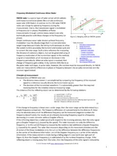
10 A. Balanis, Modern Antenna Handbook. John Wiley & Sons, Incorporated, google-Books-ID: = 10 23 / . Do not confuse this K with the chirp FMCW Radar basics7 FMCW Radar SystemFig. 3: Maximum range of a target versus minimum required SNR at the based band. The gain of Tx/Rx antennas arethe same as figureFig. 3, is plotted versus minimum SNR with values annotated. In fact, = 2is an approximatevalue for a human as mentioned in3. The transmit power of 12 dBm is the output power of AWR1642/AWR1443 chips(see table ref{TIParams}). Range detectionFromeq3andeq4, ( )can be approximated by samplingx(t): ( ) = 4 0+ ( 0) , = 4 0 ,(7)where 0is any time in[ , ]. This equation is used to detect the range of a subject, 0.