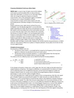
Transcription of Imaging Radar Using Cascaded mmWave Sensor Reference ...
1 TX1TX2 TXN.. d2dN1 TIDUEN5A June2019 RevisedMarch2020 SubmitDocumentationFeedbackCopyright 2019 2020,TexasInstrumentsIncorporatedImaging RadarUsingCascadedmmWaveSensorReferenceD esignDesignGuide:TIDEP-01012 ImagingRadarUsingCascadedmmWaveSensorRef erenceDesignDescriptionThis referencedesignprovidesa foundationfor aCascadedImagingRadarRF supportlong-rangeradar(LRR)beam-forminga pplicationsas well as medium-range(MRR)and short-rangeradar(SRR)MIMO applicationswith AWR2243 CascadeRadarRF developmentkithas beenusedto estimateand trackthe position(inthe azimuthalplane)beyond350 meterswith a multi-device, ,thissystemhas demonstratedazimuthangularresolutionsas smallas degreesin a datapresentedin this designguidewas obtainedusingMMWCAS-RF-EVMR evisionC, that ,the latestMMWCAS-RF-EVMR evisionD makesuse of the secondgeneration, AWR2243solutionshouldbe referencedfor E2E supportforumsFeatures Two or four-chipFMCW radarsensorfor LRR,MRR,and SRRapplications Detectobjects(for example,cars and trucks)at adistancebeyond350-mwith rangeresolutionof 35cm.
2 HumanRCSobjectsdetectableat a distanceof150-m Antennafield of view 70 with angularresolutionof degrees MATLABMIMOand beamformingexamplecodeprovided AWR2243baseddemonstrationdesign Cascadedimagingradarfrontend beamforming,and MIMO configurationfully explainedApplication Longrangeradar Imagingradar June2019 RevisedMarch2020 SubmitDocumentationFeedbackCopyright 2019 2020,TexasInstrumentsIncorporatedImaging RadarUsingCascadedmmWaveSensorReferenceD esignAn IMPORTANTNOTICEat the end of this TI referencedesignaddressesauthorizeduse, intellectualpropertymattersand otherimportantdisclaimersand a vehicleprovidesquality-of-lifeand safetybenefitsin additionto makingthe relativelymundaneact of drivingsaferand less quality-of-lifefeaturesincludethe abilityof a vehicletoparkitself,or to determinewhethera lane changeis possible,and providefeatureslike automaticcruisecontrol wherea vehiclemaintainsa constantdistancewith respectto the car aheadof it, essentially,trackingthe velocityof the car in frontof it.
3 Autonomousbrakingand collisionavoidanceare safetyfeaturesthat preventaccidentscausedby observingthe areainfrontof a car and alertingthe ADAS subsystemsif obstaclesare observedthat are likelyto hit the varietyof sensorsto detectobstaclesin the environmentandtracktheirvelocitiesand (FMCW)radarsallowthe accuratemeasurementof rangeandrelativevelocityof obstaclesand othervehicles;therefore,radarsare usefulfor autonomousvehicularapplications(suchas parkingassistand lane changeassist)and car safetyapplications(autonomousbreakingand collisionavoidance).An importantadvantageof radarsovercameraand light-detection-and-ranging(LIDAR)-based systemsis that radarsare relativelyimmuneto environmentalconditions(suchasthe effectsof rain,dust,and smoke).FMCW radarscan workin completedarknessand also brightdaylight(radarsare not affectedby glare)becausethey transmitand ultrasound,radarstypicallyhavea muchlongerrangeand muchfastertime oftransitfor manyadvantagesof radartechnology,in manycases,automotivemanufacturerstodayst illuse camerasensorsas the primarysensortechnologyusedto makefinal safetydecisionsin the radarsensoris beingusedas the secondarysensor;meaning,the vehiclesystemreceivesthe Radarwarning,but decidesto take an actiononly uponthe mainreasonislimitationin radarsensorsdeployedtodayin mostvehicleslack the abilitytodistinguishbetweenstaticobjects with the samerangeand ,a typicalfrontradarsensorhas abouta 5-degreeangularresolutionthat correspondsto the abilityof the sensorto distinguishbetweenobjectsthat are m apartat 100 m.
4 Objectsthat are m appearas one example,a vehiclestoppedin the rightlane,mightlook like a shoulderroadstreetlampfor example,and thereforewouldbe ignoredby the is aboutto changewith the introductionof the ImagingRadarsolutionfromTexasInstruments (TI).The TI ImagingRadaris a four-chipcascadesolution,that acts like a single-chipsensorbut achieves20 Log10(NTX) SNRgain in TX beamformingmodeand 360/(N*pi)angularresolution(N is the numberofvirtualantennasin a MIMO configuration).Usingthe TI ImagingRadarsolution,we can degreesapartwith allantennaeplacedin singledimensionlinearly,and reacha 350-mobjectdetectingrange(angularresolut ionis dependenton the antennaconfigurationand the numberof TX/RXantennae).This performanceenablesTI ImagingRadarto becomethe primarysensorin the vehicleand enhancesafetyacrossweatherand visibilityconditionsby providinga high-resolutionimagefor CascadeRadarDesignTIDEP-01012is an introductoryapplicationthat demonstratesbotha long-rangebeam-formingconfiguration,and a shorterrange, referencedesigncanbe usedas a startingpointto designa standalonesensorfor a varietyof long rangeand TI CascadeRF referencedesignhas demonstratedautomobiletargetdetectionine xcessof 350 m alongwith June2019 RevisedMarch2020 SubmitDocumentationFeedbackCopyright 2019 2020,TexasInstrumentsIncorporatedImaging RadarUsingCascadedmmWaveSensorReferenceD esignThe flexiblechirpand frametimingengineavailableon the AWR2243device(similarto otherAWRfamilymmWavesensors)
5 Allowsthe systemto functionas a multi-moderadar,interleavingbeam-forming andMIMO configurationson a per enablesthe sensordesignerto achievebest rangeandbest angularresolutionacrossthe arrayof CascadedAWR2243devicesas the , Cascaded ,AWR2243devicesprovidesensordes ignerswithhigher-outputpowerand thereforelower-detectabletargetRCS,or increasedrangedetection,or automobile,motorcycle,pedestrian,signage ,bridges,and otherroadwayobjectsand barriersat or beyond350-mrangecan use this modeof medium-rangeapplications(150m ranges),creatingMIMO antennaarraysacrossmultiple, Cascaded ,AWR 2243devicesallowsthe sensordesignerto maximizethe numberof enablessub 1 degreeresolution:true AWR2243 Four-DeviceCascadeRadarRF June2019 RevisedMarch2020 SubmitDocumentationFeedbackCopyright 2019 2020, SystemSpecificationsThis referencedesignhas two sets of specificationsbecausethe radaris usedas a the first beamforming(TXBF)is the secondspecification,Table1. Key SystemSpecificationsPARAMETERSSPECIFICAT IONS(MIMO)SPECIFICATIONS(TXBF)DESCRIPTIO NM aximumRange150 m350 mThis representsthe maximumdistancethat the radarcandetectan objectrepresentingan RCSof approximately10m2 RangeResolution60 cm150 cmRangeresolutionis the abilityof a radarsystemto distinguishbetweentwo or moretargetson the samebearingbut resolutionis configurable,so the providednumberis just an degrees(withmultiplebeamsteering)
6 Angleresolutionis the abilityofa radarsystemto distinguishbetweentwo or moretargetswith the samerangeandvelocitybut resolutionis degreesn/aElevationangleresolutionisonly availablefor MIMO applicationgiventhe antennadesignon the TI kmph133 kmphThis is the nativemaximumvelocityobtainedusinga two-dimensionalFFT on the TDMMIMO case,velocitycompensationalgorithmis appliedto recoverthe specificationwill beimprovedovertime by showinghow higher-levelalgorithmscan extendthe maximummeasurablevelocitybeyondthis parameterrepresentsthecapabilityof the radarsensortodistinguishbetweentwo ormoreobjectsat the samerangebut movingwith June2019 RevisedMarch2020 SubmitDocumentationFeedbackCopyright 2019 2020, showsthe blockdiagramof the cascadeRF CascadeRadarRF June2019 RevisedMarch2020 SubmitDocumentationFeedbackCopyright 2019 2020, AWR2243is an integratedsingle-chip,frequencymodulated continuouswave(FMCW)sensorcapableof operationin the 76 to 81 deviceis built with TI s low-power,45-nmRFCMOS processorand enablesunprecedentedlevelsof analogand digitalintegrationin an devicehas four receiversand threetransmitterswith a closed-loopphase-lockedloop (PLL)for preciseand programmable6-bitphaseshifter( )to includestwo 20-GHzlocaloscillator(LO)outputand two 20-GHzLO inputpathsfor sharingthe VCOoutputwith enablesa cost-effective,totallypassive, sensorincludesa built-inradioprocessor(BIST)
7 For RF calibrationand ,the sensordevicesupportsan IF bandwidthof 15 MHzwithreconfigurableoutputsamplingrates in bothcomplexand real separateArm Cortex -R4 Fbasedprocessorsrun the TI providedradarfront-end,calibration,and host BoardFeaturesCascadeRadarRF Board4 AWR224376-81 GHzRadarSoCIntegratedVCO,LO distribution,PA, LNA,ADC,3 TX and 4 RXArm MCUR4 ControllerAWRRF Peripherals12 TX, 16 RX Antennas12 total transmittersacrossall 4 AWR2243devices16totalreceiversacrossall 4 AWR2243devicesAzimuthArray86 elementvirtualarray degreeangularresolutionElevationArray4 elementvirtualarray enabling18 degreeangularresolutionEmbeddedAntennaRo gersRO30034-element,series-fed,patchante nna20 GHzLOStarDistribution2 passiveWilkinsonPowerdividersfed by the MasterAWR2243deviceLO outputto ,max dataper deviceQSPIF lash16 MbitQSPI flashfor AWRfirmwareupdatesSerialPeripheralsSPI, I2C, UART,GPIOS ystemTemperatureTMP112I2C TemperatureSensorsPowerRadarPowerManagem entIC (PMIC)Solution2 LP87524P-Q1 Quad-Channel,IntegratedFET,BuckConverter sand LC BoardArchitectureThe AWR2243 CascadeRF boardconsistsof four AWR224377-GHzradardevicesand theirassociatedpower,clocking,synchroniz ation,LO, and RF , RX, and TX port is routedto its own set of etched, the RF boardhas a is usedfor sendingradardatato a host The entireAWR2243configuration,control,and resetlinesare madeavailableon twohost-interfaceconnectorsimplementedwi th (Master)AWR2243 AWR2(Slave)AWR2243 AWR3(Slave)AWR2243 AWR4(Slave)FMCW_CLKOUTL ength: BFMCW_CLKOUTL ength: BFMCW_SYNCOUTL ength: BFMCW_SYNCOUTL ength: BWilkinsonPowerDivider 1 WilkinsonPowerDivider 2 FMCW_CLKOUTL ength: AFMCW_SYNCOUTL ength.
8 AAWR2243 AWR1(Master) June2019 RevisedMarch2020 SubmitDocumentationFeedbackCopyright 2019 2020,TexasInstrumentsIncorporatedImaging RadarUsingCascadedmmWaveSensorReferenceD esignThe AWR2243devicesare separatedinto masterand #1, the masterdevice,usesthe AWR2243architecturebuilt in LO distribution,clockdistributionand framesynchronizationdistributionto provide40-MHzclock,20-GHzLO and digitalframesynchronizationtootherthrees lavedevices AWR2243#2, #3 and #4. This allowsthe systemto generateand receivecoherentFMCW chirpsacrossthe 4 AWR2243devicearrayof transmittersand receivers;enablingbeam-formingand MIMO operationacrossthe arrayof 20 GHzLO distributionfollowsthe start-networkconfigurationdescribedin the AWR2243 CascadeRadarApplicationNote, masterAWR2243#1 feedinga networkof two Wilkinsonpowerdividers,that providesynchronousLO for the Masterand SlaveRF PA and ,synchronizationdistribution,and LO distributionrequirementsare documentedin CascadeRF boardaccepts5V DC, 8 A (max)powerthroughthe host primary5 V systemrail can be convertedinto the variousAWR2243devicerails by a pair of LP87524P,quad-channel,monolithic, GHzLocalOscillator(LO)Distribution20-GHz LO distributionto all AWR2243devicesis accomplishedthroughan entirelypassive,transmission-lineand usingthe dual LO outputsand LO inputsprovidedon eachAWR2243device,all devicesincludingthe masterdevice,receivethe samemasterdevicegeneratedLO resultsin all packageand die routingdelayscommonacrossall left with the task of delaymatchingonly the BGAto usingbothof the 6-dBm(typical)
9 LO output,and minimizingtransmissionline and powerdividerlosses,no externalamplifiersare requiredto be addedto the LO ,by outputting20 GHzLOversusfull 77-GHzRF for RF synchronization,the LO PCBlink budgetscan be passiveLO distributionnetworkand relaxedlink budgetresultsin morePCBdesignflexibilityand showsthe blockdiagramof the delaymatchedLO showsthe implementedWilkinsonpowerdividersin AWR2243devicesand powerdividersis majorityof the LO distributionlengthis carriedthroughan 20 GHzLO June2019 RevisedMarch2020 SubmitDocumentationFeedbackCopyright 2019 2020,TexasInstrumentsIncorporatedImaging RadarUsingCascadedmmWaveSensorReferenceD esignFigure4. 20 GHzLO DistributionBoardImplementation3 SystemDesignTheoryThe CascadeRF MIMOand beamformingantennadesign,chirp,and frameconfigurationare systemvariablesthat mustbe co-designedfor a antennaarray,MIMO chirp,andbeamformingchirpdesignare showsthe antennaarrayon the CascadeRF boardwith one masterdeviceand total of 12 TX channelsand 16 RX 12 TXchannels,the threeTXs (TX1/2/3)fromthe masterdeviceare placedin the verticaldirectionfor remaining9 TXs (TX4throughTX12)and all 16 RX channelsare placedin thehorizontalplanefor relativedistancesbetweenTXs and betweenRXs areshownin Figure6.
10 The threeelevationantennasare placedto forma azimuthTXs are spaced2 arrayAand RX arrayC are arrayC and RX arrayB are virtualarrayin MIMO modeis shownin Figure7, with 86 overlappedantennain azimuthis not shownin the elevationangleresolutionis equivalentto the resolutionachievedwith 7 unit is ARRAY-BRX ARRAY-C2-chip cascading distance is to meet 2-chip cascading requirement (azimuth and elevation) June2019 RevisedMarch2020 SubmitDocumentationFeedbackCopyright 2019 2020,TexasInstrumentsIncorporatedImaging RadarUsingCascadedmmWaveSensorReferenceD esignFigure5. Deviceand AntennaArrayGroupsThe CascadeRF boardcan also be usedin two chip cascademodewith 6 TX and 8 RX channelshighlightedin Figure6. Figure8 showsthe virtualMIMO arrayin 2-devicecascademodeusingTX ID of [12 3 10 11 12] and RX ID of [ 4 3 2 1 16 15 14 13], with 23 azimuthantennasand sameelevationconfigurationwith June2019 RevisedMarch2020 SubmitDocumentationFeedbackCopyright 2019 2020,TexasInstrumentsIncorporatedImaging RadarUsingCascadedmmWaveSensorReferenceD esignFigure7.